Understanding Probe Issues
The V-One software now has a new feature to help users better diagnose issues they might face. One of the most important errors to catch are height related errors. The software will now compare probed points against each other to try and catch these problems.
The probing process
Before printing, we use the probe to generate a heightmap of the board surface. This is important in making sure the tips of your tools remain safely above the board. To do this we touch the board with the probe and measure its height then compare those values against each other.
You can see in the image below all of the expected probe points for the Hello World board when using default settings.

During probing you’ll notice that each point becomes filled in as it’s being measured.
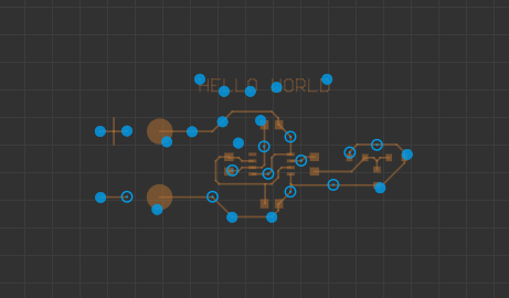
You can change the resolution of your height map by adjusting your Probe Pitch in the settings menu. Here’s an example of the same board with a Probe Pitch of 2.5mm. The value is the maximum distance between two adjacent probe points; there isn’t a minimum value.
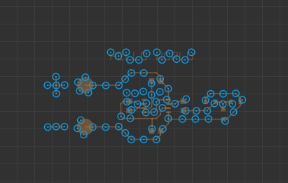
This will take longer and in most cases won’t make any improvement to your print but it’s a useful feature to be aware of.
Getting an error
Part of this process is to help prevent problems before they happen. In the example below the board was intentionally placed too far to the left so that the probe would fall off on the right side. You can see from the example that there was a problem detected with the height.
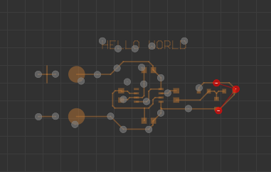
The software compares probe points that are near each other. In this case, the point to the far right of the board has a height conflict with its neighbours. Zooming in close we can see the actual values of the probe points. The lowest point overall is set to be 0 and everything else is relative to it. Because the board was missed and the probe hit the heated bed that’s the lowest point.
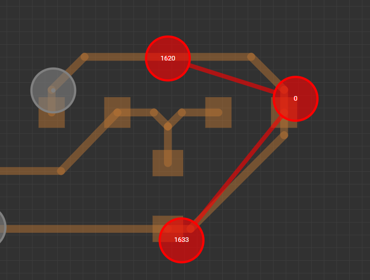
Taking a look at the values it’s pretty clear where the problem is. The values 1620 μm and 1633 μm are very close to one another while 0 μm is way off. In an instance like this, it’s wise to reprobe and pay special attention to the section of the board that’s showing the error. In this particular case it would become clear that the probe is falling off the board and the board should be repositioned.
One very common cause for a measurement like this is that a holes file wasn’t loaded along with the Gerber. If your probe falls into a hole during probing you’re going to end up with a bad height map and most likely a crashed nozzle.
It’s important to note that it’s not always the low value that’s a problem. In this next example a folded piece of paper was placed on top of the right edge of the board.
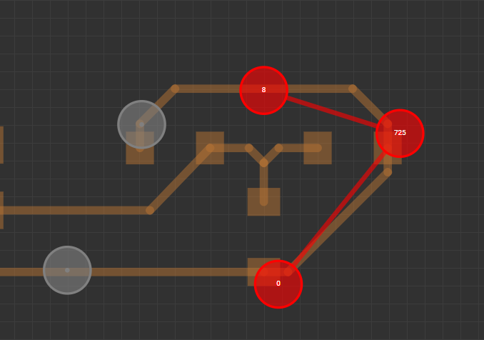
You can see that the same error is being shown but in this instance the bottom point is our lowest overall point and the point at the far right is far too high compared to its neighbours.
Want more detail?
We provide two console commands to help give you even more insight into your probing. (Open the console by pressing Alt + C)
ShowProbingTargets - will show all the probe points for the circuit at any step of the process. This can be useful if you’re having height issues and want to see your specific values near where you’re seeing issues. This command will also display the measured values for each point.
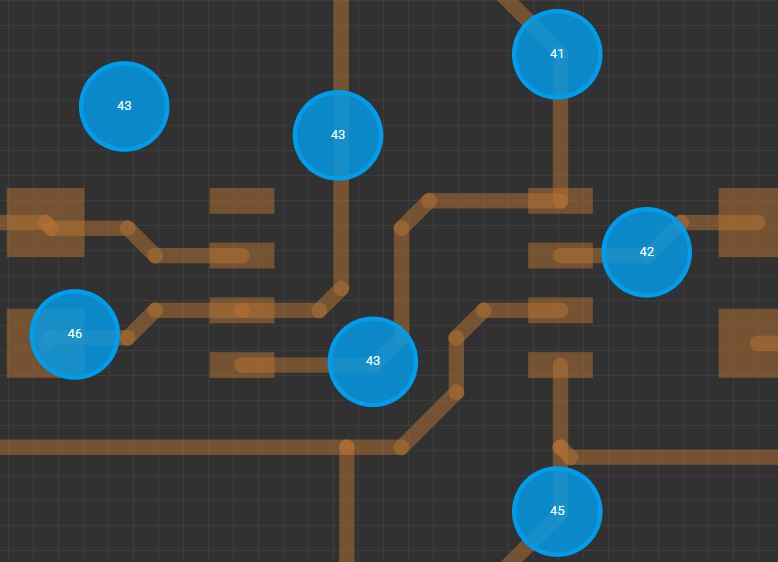
ShowHeightMap - will display the triangles that make up the heightmap of the board. This one can help to visualize how our heightmaps are generated and may help in understanding how each point relates to the other.

By default the maximum difference we allow between two points in 0.08mm. This value can be changed in the Beta tab of the Settings menu listed as Probing Error Detection

The highest the tools can be raised for Travel Height is 10mm.
Last updated
Was this helpful?