Hand Soldering to Ink
In a hurry?
In this guide, Mike runs through the key dos and don'ts for solder paste dispensing and hand soldering boards printed on the V-One. Skip to 2:28 to jump right into hand soldering!
Read this first!
Soldering to conductive ink IS NOT exactly like soldering to copper! Even if you are a soldering pro, follow this guide to ensure a good quality solder joint.
There are a few key differences when soldering to conductive ink:
Conductive ink is not pure metal, and does not conduct heat well. This means that solder will not spread as quickly or easily as on copper. Tinning the pads first and spreading the solder with the soldering iron will help produce an even coating of solder.
The silver in the traces and pads will dissolve into the solder completely if the solder is melted for too long or at too high a temperature - this is called silver scavenging. Keep the soldering iron within the recommended temperature (180°C / 355°F), and do not melt the solder for more than 30 seconds at a time.
Not all solder alloys are compatible with silver. Use only the provided solder alloy (SnBiAg1).
Getting Started
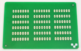
For this guide, we made a Hand Soldering Practice Board! Print one of these for yourself, and take some time to practice soldering before trying it on one of your prototypes.

Equipment
For best results, we recommend you use the following:
A variable-temperature soldering iron (preferably digital, for best accuracy), set to 180°C (355°F). Temperature control is critical for good soldering with conductive ink.
Flux. The Voltera solder wire is NOT flux-cored, meaning you MUST apply flux before soldering.
The provided solder wire. Using other solders is likely to damage the conductive ink.
A solder sponge (plain or brass) for cleaning the soldering iron.
A set of helping hands (or third hand). This isn't necessary, but will make it a lot easier to keep everything in place.

Prepare the Circuit
1. Burnish the Ink
Burnishing is only needed for Conductor 2/Flex 2 inks. Conductor 3 no longer requires the burnishing step.
Burnishing the ink exposes the silver within the ink, which gives us a solderable surface for joining components. To burnish the circuit, rub vigorously with the provided burnishing pad for 20 seconds.
You should be able to see a clear color difference between the burnished and non-burnished ink. Baked ink will appear off-white and matte, while burnished ink will appear silver and faintly shiny.

2. Drill the board
We use the V-One Drill attachment to drill our prototype PCBs in-house, but if you don't have one, a rotary tool collet and a PCB drill bit set are inexpensive and will help you drill a variety of sizes for vias and through-hole pads.
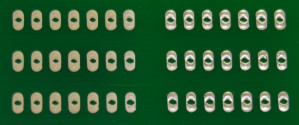
For the hand soldering practice board, we used a 0.8 mm drill bit. When drilling the board, go slowly and drill all the way through the board.
Prepare the Materials
1. Tin the Soldering Iron
Before we start soldering, we have to tin the soldering iron. This means that we'll be coating the tip of the soldering iron with solder to remove oxide and residue from non-compatible solder alloys.
If the tip is heavily oxidized, you may have to increase the temperature of the iron. Make sure to bring it back down before soldering!
To tin the soldering iron:
Turn on the soldering iron and heat to 180°C (355°F).
Feed a generous amount of solder wire in towards the tip, melting the solder. Continue until you have coated the tip.
Wipe the soldering iron down on the solder sponge to remove excess solder.
The tip should appear silver and have an even coating of solder. Repeat steps 2-3 if necessary.
2. Tin the Component Lead
Tinning the component will help with wetting and produce a joint quickly. Some components may be pre-tinned, but others, such as bare copper hook-up cable, should be tinned prior to soldering.
To tin the component:
If using hook-up wire, strip the wire to expose the bare metal. Clamp the component using the helping hands soldering tool, or some other method to free up your hands.
Bring the hot soldering iron into contact with the metal.
Feed the solder wire into the junction between the soldering iron and the metal. This should melt the solder.
Continue feeding in solder and move the iron to fully coat the lead.
If there is excess solder on the component lead, clean the tip and re-melt the solder to clean up the component. We want a thin layer of solder, not globs.
Solder the Board
1. Tin the Pads
Tinning the pads is crucial for a smooth soldering experience. Just like with the soldering iron, tinning the pads just means coating them in a film of solder to promote wetting and creating a uniform solder joint.
If you have ever ordered PCBs from a fab shop, you may have noticed that the exposed pads appear silver, rather than copper in color. This is because the pads are coated in a layer of metal to help promote soldering and prevent oxidation. Typical metals include leaded or lead-free solder alloys (HASL), tin (ISn), nickel (ENIG), or gold. With conductive ink, we need to tin the pads ourselves to get the benefits that come with a metal finish.
To tin the pads:
Make sure the soldering iron is clean and heated to 180°C (355°F).
Apply flux generously to the pads - remember, the wire is not flux-cored!
Bring the soldering iron into contact with the conductive ink pad. If using a thin conical tip, use a thicker portion of the tip (about halfway up) to help melt and spread the solder.
Feed a small amount of solder into the junction between the soldering tip and the pad, melting the solder.
Pass the soldering iron over the pad, spreading the solder. You should see a coating of solder on the pad.
Clean the tip between each pad. We don't want a large glob of solder on the tip - this can negatively impact solder wetting.
You don't need a large amount of solder on the pad - even a small coating will help with wetting. Repeat steps 3-4 if necessary, but refrain from melting the solder for too long.
2. Solder the Components
All that's left is to solder the components! In this example, we are using unshrouded male pin headers.
Use the helping hands soldering tool to secure the board, and insert the component leads into the drilled hole. If the component is loose, secure it as well.
Bring the hot soldering iron into contact with both the component lead and the tinned pad. As before, use a thicker portion of the tip to help distribute heat.
Feed a generous amount of solder into the junction between the soldering iron, component lead, and pad. You should see the solder wet the pad and create a fillet around the component.
Bring the soldering iron to the other side of the component lead and repeat. Ensure that the joint is complete on all sides of the pad.
Clean the soldering iron tip between each pad!
Soldering hook-up wire is straightforward as well, if you would like to connect your circuit to a different board or device.
3. Clean up the Solder Joints
The solder should form a uniform fillet around the component. If there is a spherical glob of solder, there is too much and it needs to be cleaned up. To clean up the solder joint:
Apply a generous amount of flux to all sides of the solder joint.
Bring the soldering iron in contact with the solder joint. The flux will help the solder melt rapidly, and excess solder will coat the soldering iron.
Remove the iron from the joint and keep the component stationary as the solder cools.
The solder joint should now be a uniform fillet. Repeat steps 1-3 as necessary, but refrain from melting the solder for more than 30 seconds to prevent the silver from dissolving.
Last updated
Was this helpful?