

3. Drilling the Holes
Punk Console: Drilling
Software
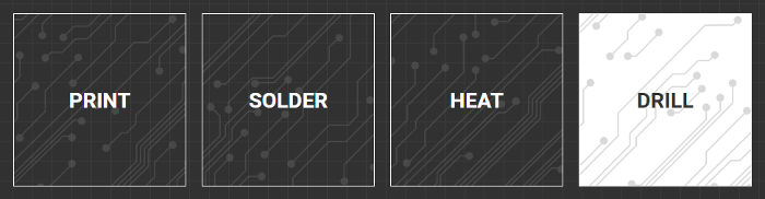
1. Open the drill workflow
Open up the software and jump into the DRILL workflow. Since we are not going to be aligning to any existing features, choose SIMPLE alignment.
2. Load your file.
Download the Punk Console Gerbers here and load the following files:
Follow along with the software as we complete the workflow.
Drilling
1. Clamp your board
When drilling boards on the V-One, it is important to protect the heated bed and the drill bits from any damage. The drill bits must travel all the way through the substrate to create a clean hole.
The sacrificial layer offers this protection and needs to be mounted directly on top of the heated bed. Use the long thumbscrews provided to secure your clamps and hold the sacrificial layer and the 2x3 FR1 substrate in place.

2. Position the circuit
With the probe mounted outline the boundary of the circuit. If the probe outline does not fall within the board boundaries, click and drag the circuit to adjust the position and outline again. For the Punk Console we want the circuit to be positioned in the center of the FR1 board.

3. Probe the Board
Outline look good? Go to the next step and click PROBE. The V-One will now automatically generate a height map of the board’s surface. This height map is critical for good quality printing.
If you need to move the board for any reason after this step, you must return and RE-PROBE!
4. Select your hole size
When selecting holes, you must indicate what drill bit size you want to start with. The software will highlight all of the holes that match the requested size. To start, let's drill the 0.70 mm holes.
Advanced users can also manually select holes they wish to drill.

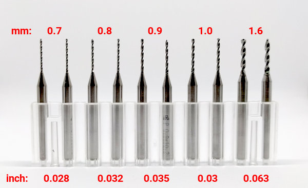
5. Installing the drill bit
Now we must install the 0.7 mm drill bit. The drill bit container has 10 drill bits with the following sizes (2 of each): 0.70 mm, 0.80 mm, 0.90 mm, 1.00 mm and 1.6 mm. Left to right, they increase in size.
The bits are also engraved with their size in millimeters. The one shown below is 0.7 mm.
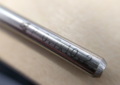
Use the provided 1.5 mm hex key to install the drill bit. Make sure the bit is deep enough in the coupler so the shaft is not visible.

6. Mount the drill
Mount the drill on the carriage and connect the power adapter. Rotate the power adapter so the cable is in a downward position and slide the drill up so it is at the top of the mounting rails.
When the V-One Drill is powered and mounted on the V-One, the drill will enable the motor and an audible startup sequence (beeping) will be heard. This is normal operation. You should also see both green LED indicator lights come on.

Once you are good to go, put on your safety glasses and hit next.
Always wear safety glasses when drilling with the V-One, to protect eyes from any debris
7. Start drilling!
Click DRILL to begin drilling!
Important: As a safety precaution, the drill will immediately stop spinning when removed from the V-One.
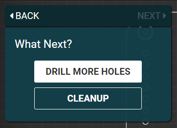
8. Keep drilling!
After all of the 0.7 mm holes are drilled, unplug the drill power cable and remove the drill from the V-One carriage. You can then swab out the 0.7 mm drill bit for the 1.6 mm drill bit using the 1.5 mm hex key.
Once you have swabbed the bit, remount and power on the drill. You can then click the 'Drill More Holes' button to start drilling the 1.6 mm holes. The software will indicate which holes are left.
9. Cleanup the workspace
After all the drilling is completed. Be sure to clean up the debris with a vacuum or damp cloth. We are going to print on top of the holes now, so it is very important to leave the substrate clamped down and do not move it!
Do not move the substrate! We are going to print next!
Let's start printing the top layer of this circuit! Follow along in the next section
Last updated
Was this helpful?