

Port & Camera Alignment Calibration
Why do the Calibration?
The XY positioning system on NOVA assumes that the nozzle tip’s cross-section is symmetrical. Ideally, when the tip is perfectly perpendicular to the XYZ knob, there is no positional variance in how the tip is measured. However, slight deviations in gantry alignment or inconsistencies in the nozzles or couplers will affect the accuracy of the XY positioner, especially with conical nozzle geometries. This is due to the nozzle tip not being concentric with the section of the nozzle contacting the XYZ.


This alignment calibration procedure helps resolve this issue by calculating and storing scaled values that can be applied to a tools position relative to the camera position. The end result is more reliable camera and tool alignment when printing.
Is My NOVA Already Calibrated?
If your printer shipped in the fall of 2024 or later there is a chance that this calibration has been done during the production of your machine. To check if the alignment calibration has been done you can run a command in the NOVA software.
For this you'll need to have your printer on and connected. Then, in NOVA's software press the ~ button on your keyboard to open up the console. Type in M520 in the console and hit enter, it will give you an output that looks like this:

Under the Alignment Coefficients section you should see two sets of values, one for each port (P0 and P1). If there are values listed for both ports the calibration has been done already:
log: M511 P0 A:0.005802 B:0.029999 C:0.016120 D:0.020005
log: M511 P1 A:0.001933 B:-0.010009 C:0.012896 D:0.009995
If there values all 0.000000 for either or both ports then calibration needs to be performed:
log: M511 P0 A:0.000000 B:0.000000 C:0.000000 D:0.000000
log: M511 P1 A:0.000000 B:0.000000 C:0.000000 D:0.000000`
Follow the next steps to perform the alignment calibration.
Calibration Overview
Tools needed:
2 x swivel mount thumbscrews from rigid mounting hardware
1 x Subrex nozzle, 100 µm preferred but 150 µm or 200 µm will work
The calibration was introduced in software version 1.15, so you will need to be on that version or later to perform the calibration. You can check your software version in the bottom right corner of the software.
The calibration works is as follows: First move the camera crosshair so that it is over the putty on the jig. Then tell NOVA to plunge the nozzle tip into that same spot. This leaves a small mark in the putty so that when camera moves back to that position there is a reference point to see if it is off center. Finally, the camera is manually centered on the mark in the putty and then the calibration values are calculated and stored. This is done on the lower level of the jig and then on the upper level of the jig for both ports on NOVA. Once complete, NOVA will have scaled values that align the tool position to the camera at any substrate height.
3D Print the Jig
If you'd like to 3D print the jig for yourself rather than ordering it from us you can use the file below to do so. Standard print settings with your printer will provide more than enough accuracy for the part. Once printed, you can fill the cavities flush on each level with silly putty. Wearing gloves will keep the putty from picking up too much debris from your surroundings.
1. Calibration Setup
Mount the calibration jig onto the print area using two of the swivel mount thumbscrews from your rigid mounting hardware. Make sure it's centered from left to right with the taller section facing the front of the machine. Leave one row of holes between the calibration plate and the fixture:

Attach a Subrex nozzle to a pressure sensor and install the pressure sensor in your dispenser. There is no need for an ink cartridge for this procedure.

2. Navigating to the Alignment Calibration Procedure
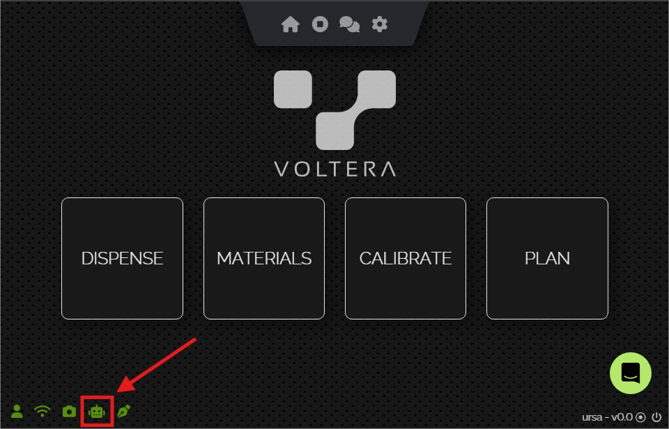
From the main page of NOVA's software click the Gantry Settings (robot) icon in the bottom left hand corner:
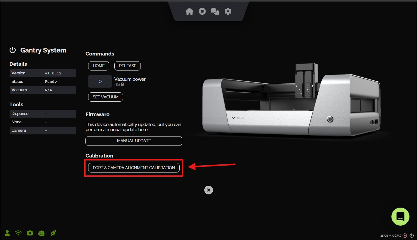
Click the Port & Camera Alignment Calibration button:
3. Reset Compensation
If this is the first time running through the calibration or you'd like to redo the calibration, click the 'Reset Compensation' button to clear any alignment compensation values already saved to your NOVA:

4. Calibrating the First Port
Mount the dispenser with the Subrex nozzle installed to the port that you wish to start with. Then make sure that you have selected the matching port with the 'Port' toggle switch:

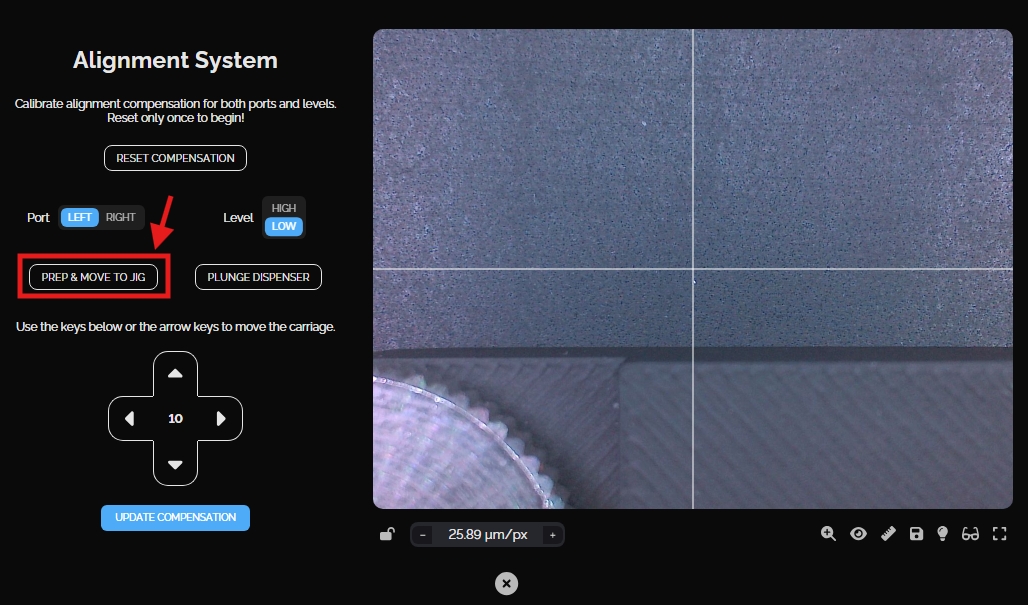
We will start by measuring at the lower level of the jig by selecting the 'Low' option on the Level toggle.
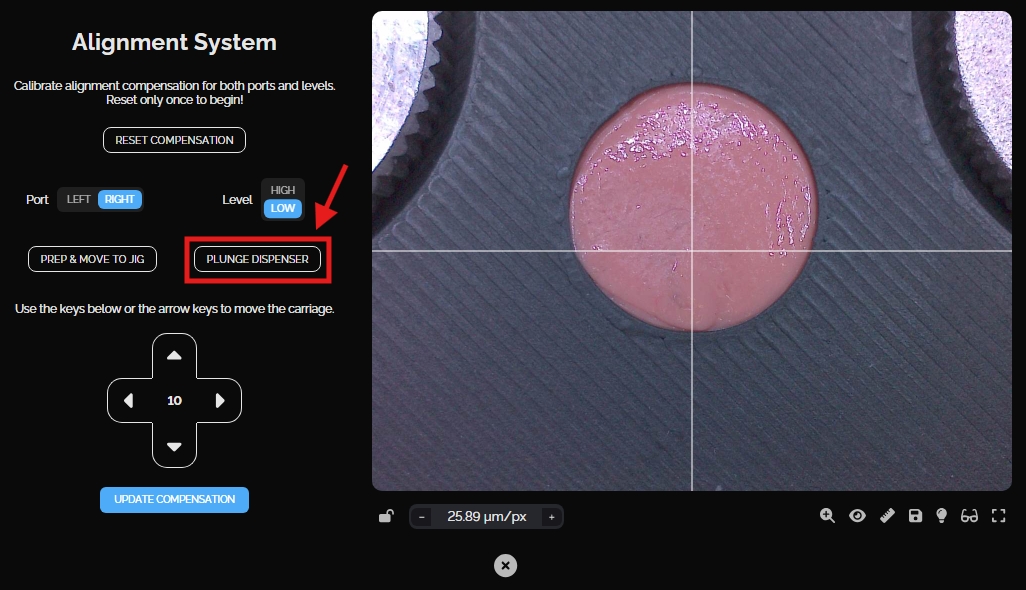
Click the 'Prep & Move to Jig' button. This will prepare the camera and dispenser on the XYZ positioner (if needed) and then move the camera to view the jig:
If the camera ever seems out of focus, click the eye icon under the camera feed to autofocus the frame. This can make aligning the crosshair easier.

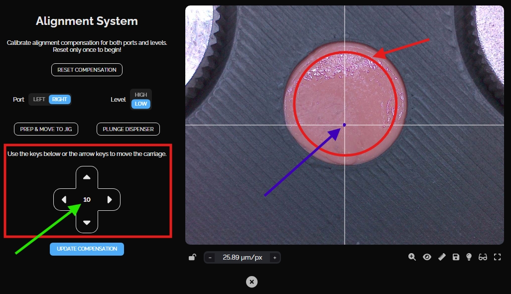
Using the directional arrows (or keyboard arrow keys) center the camera crosshair (shown in blue) within a central region of the circular putty (shown in red). To change the mm step size of the movements, click the number within the arrows (shown in green).
Click the 'Plunge Dispenser' button to poke the putty at this location. The dispenser will move to poke the putty at the position of the camera crosshair, it will then move the camera back to the same position.
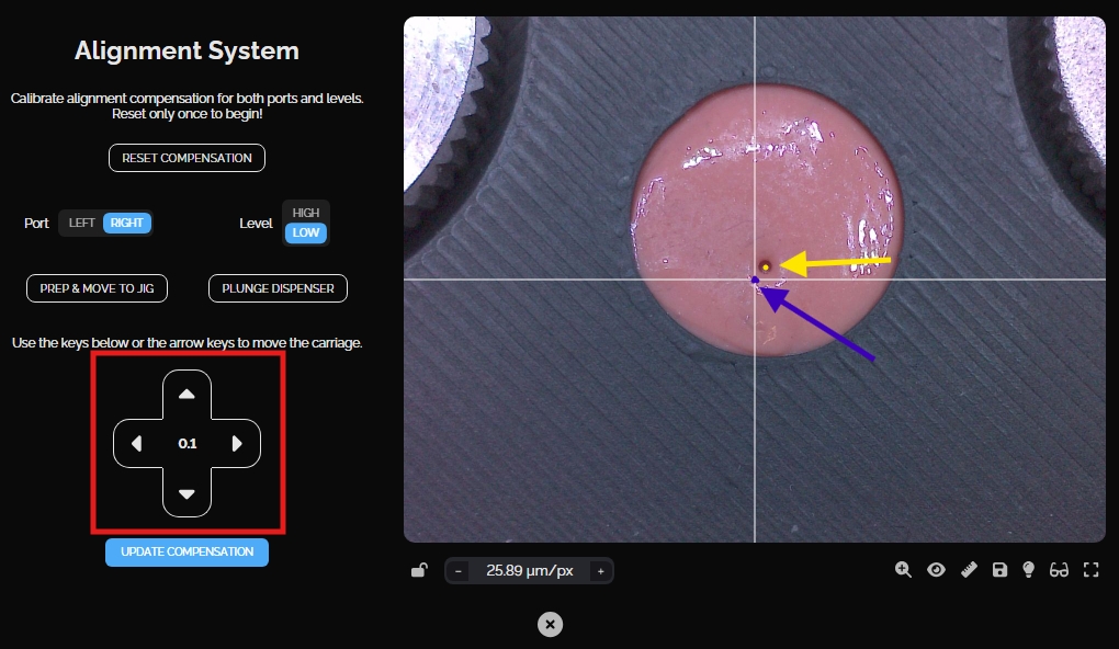
If the crosshair is not centered on the hole, use the arrow keys to move the center of the cross hairs (shown in blue) to line up with the center of the poked hole (shown in yellow):
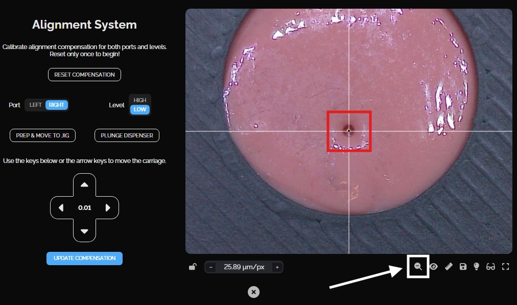
To get a clearer view click the zoom icon (shown in white):
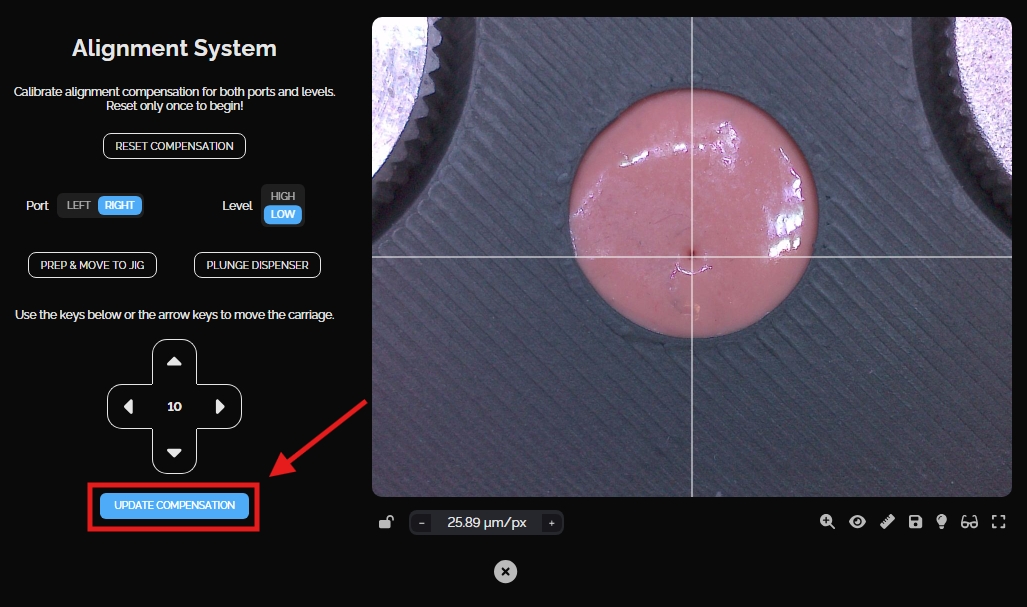
Once the crosshair is perfectly centered, click the 'Update Compensation' button to save the compensation data for that location.
Once finished on the lower level, select the 'High' option on the Level toggle, and repeat the steps to calibrate the compensation for the upper level (Prep & Move to Jig > Plunge Dispenser > Recenter Crosshair > Update Compensation).

5. Test Calibration
After completing both levels on a port, test the new calibration by manually adjusting the camera 2 mm away from the hole in any direction using the arrows. Then, click the 'Plunge Dispenser' button to make a new hole and have the camera move back. The camera should be centered on the new hole showing that the tool and camera are calibrated.
If the camera does not return to the center of the hole the calibration is off and the procedure will need to be done again. This will require resetting the compensation with the button at the top of the page and repeating the process again on both levels.
6. Repeat for Second Port
Once both levels are complete for one of the ports, remove the dispenser and remount it onto the other port. Remember to update the port toggle to match and set the level to 'Low' again. Reset the putty by smudging the surface with a finger or thumb to erase the existing holes. Then go through the same steps ( 4. Calibrate the first port & 5. Test calibration ) to calibrate on the lower and upper levels.

Calibration Complete!
With both ports calibrated and tested the calibration is complete. This process doesn't need to be done regularly. It's only necessary if the machine doesn't have calibration values set or if a dispenser has been swapped out for a new one (due to repair or replacement). But, it's a good idea to store the calibration jig for future use if needed. It should fit perfectly in the foam insert in NOVA's drawer.
Last updated
Was this helpful?