

X-carriage PCB Replacement
Safety first! Before starting any repair, take a moment to review the safety information in your user manual. An online version of the guidelines can also be found here.
Before you begin
This guide will take you through replacing the X-carriage PCB in NOVAs bridge. Before beginning this guide you should have been in contact with our support team and received replacement parts and calibration jigs.
Before beginning this procedure you should have NOVAs bridge removed following the NOVA bridge replacement guide up to the Installing the new bridge section.
As you work through this guide please reach out to our email [email protected] or through the chat if you run into any issues or have any questions. We are more than happy to assist you virtually with this repair.
When in doubt, reach out!
Estimated Repair Time:
3 hours (including bridge removal)
Tools you will need:
Screwdriver
T20 Torx
T10 Torx
T6 Torx
3mm hex key
A tray or container for screws
Parts you have received from Voltera:
X-carriage PCB
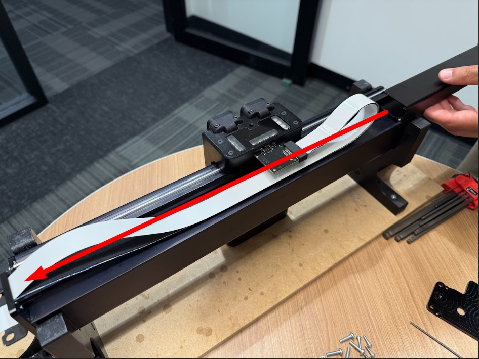
Bridge setup
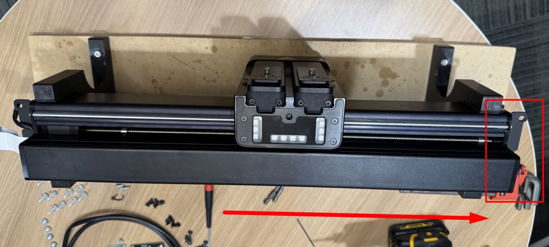
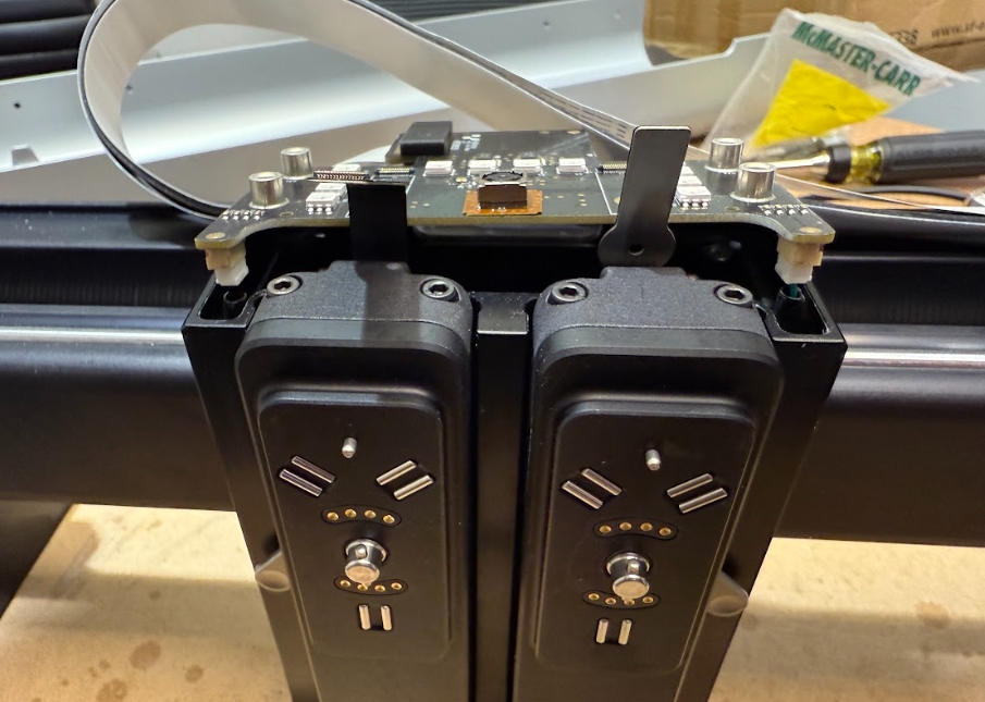
With the bridge removed from NOVA place it on a flat, sturdy working surface.
Ensure you have enough working room and a secure place to store loose screws and hardware.

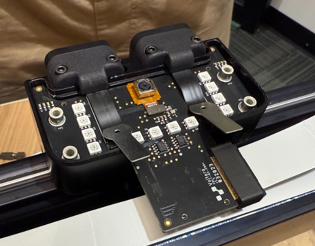
Remove the X-carriage PCB
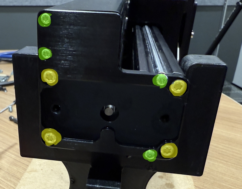
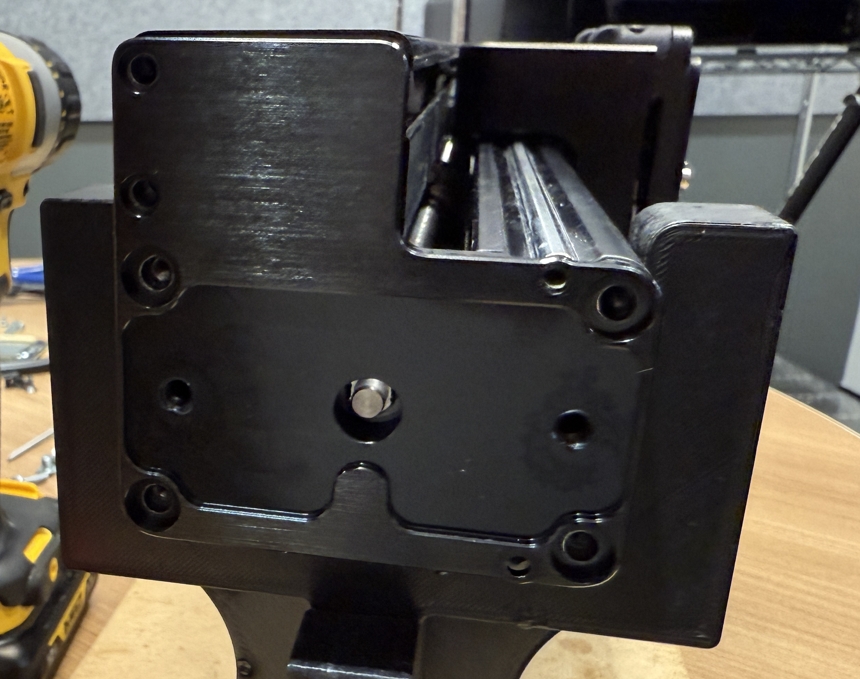
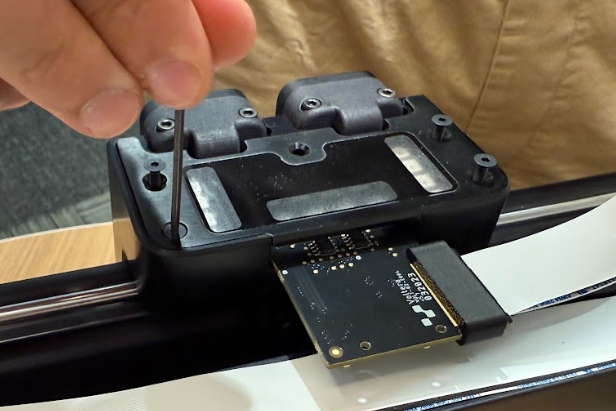
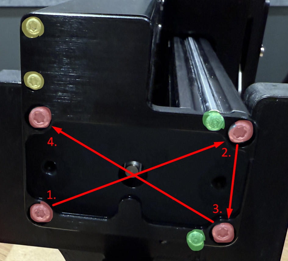
To access the x-carriage PCB we need to remove the right bridge end plate and slide out the cable tray.
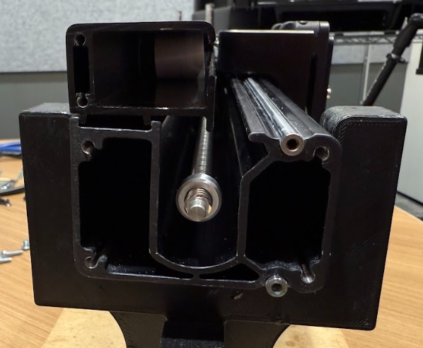
Remove the X-carriage PCB
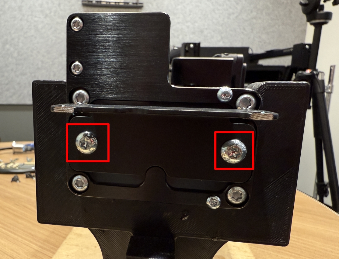
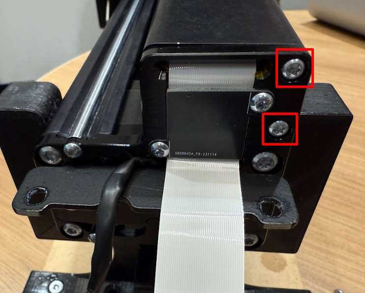
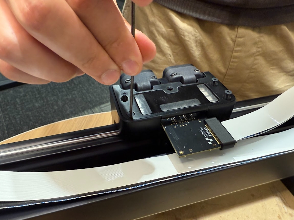
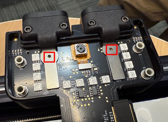
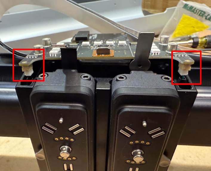
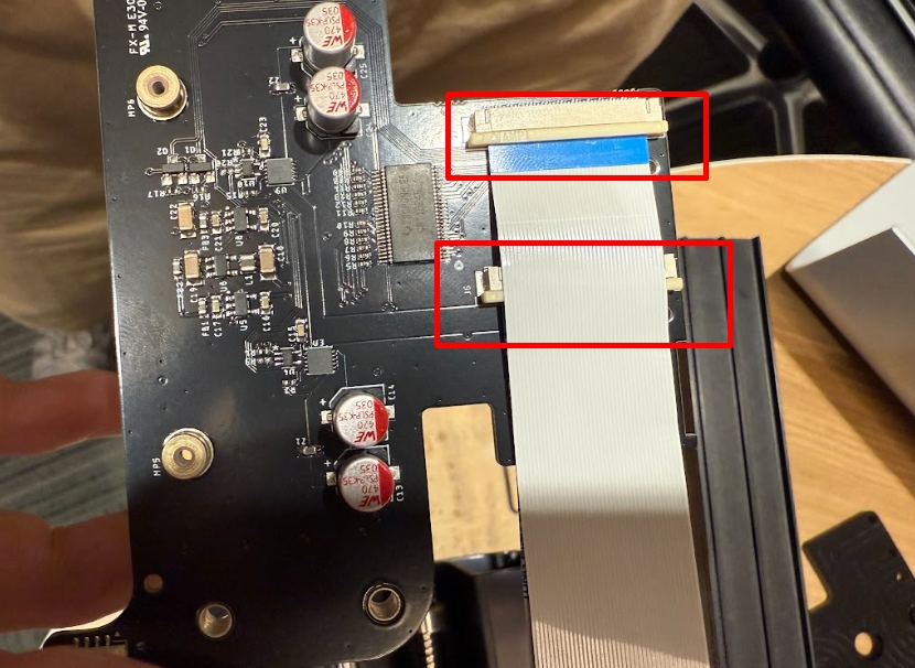
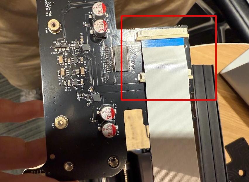
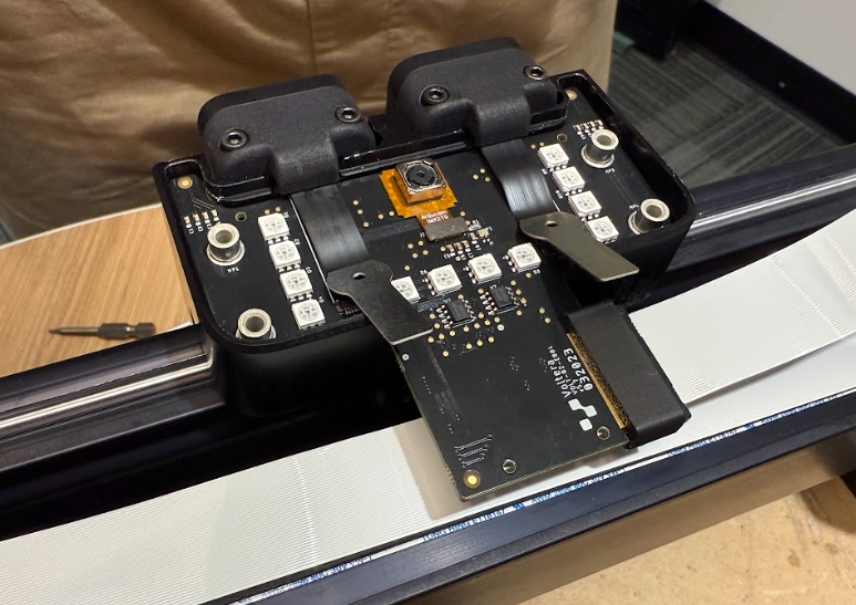
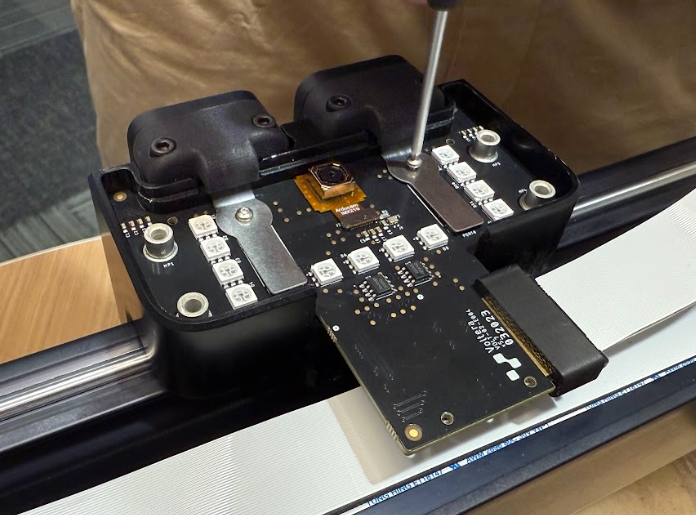
Use a screwdriver and T6 torx bit to remove the two screws securing the port connectors to the x-carriage PCB.
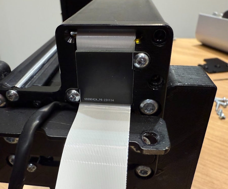
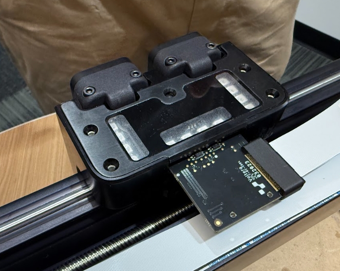
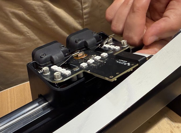
Disconnect the port flex cables from the x-carriage PCB by using your fingers to lift up on the metal tabs.
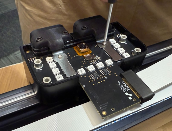
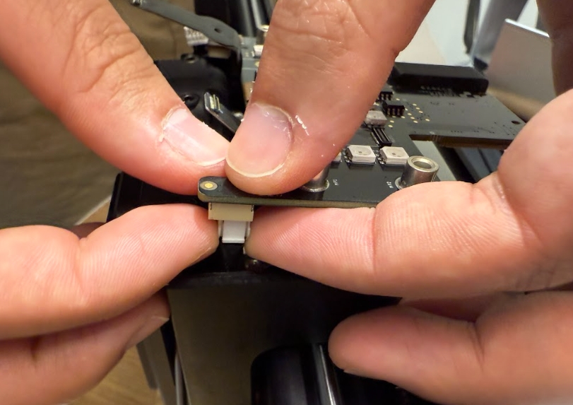
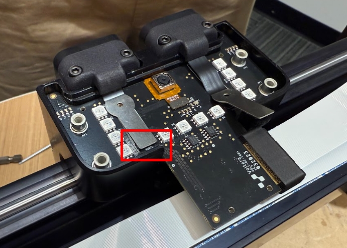
Lift the x-carriage PCB out of the bridge and disconnect the left and right motor wire harnesses on the backside of the board by pinching the release tab on either connector.
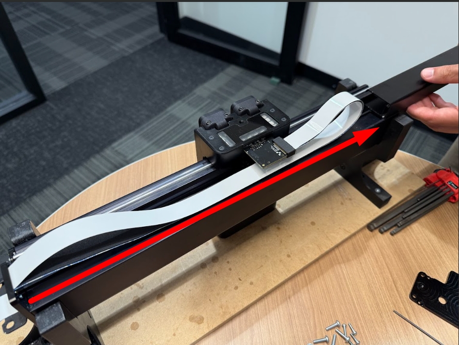
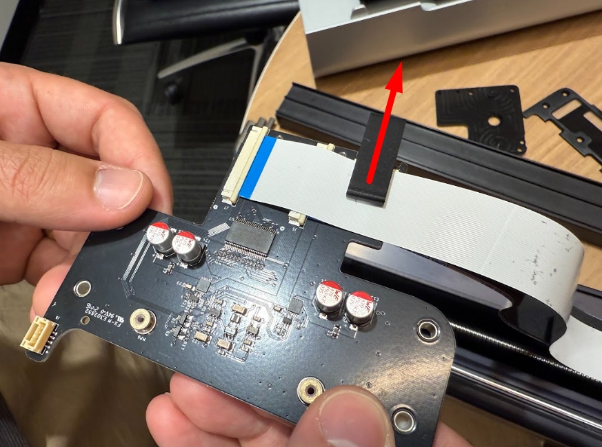
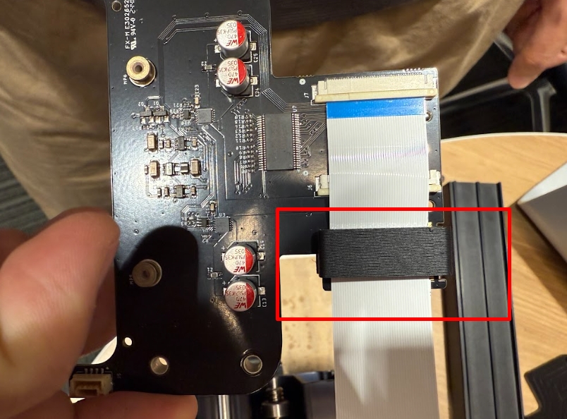
With the x-carriage board loose from the bridge, remove the plastic clip securing the ribbon cables and disconnect both ribbon cables.
Reassemble the bridge
Connect the new X-carriage PCB
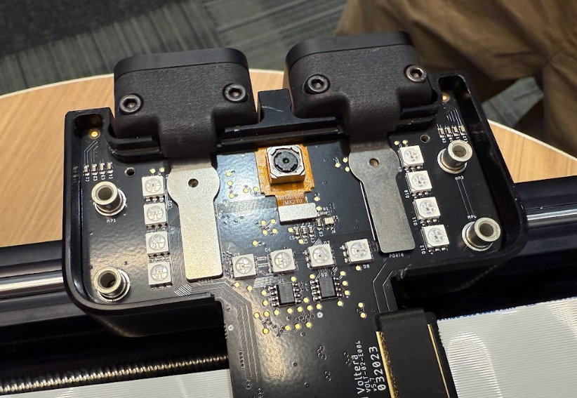
Connect the new x-carriage PCB to the ribbon cables. Ensure that the cables are fully inserted and the blue end is sitting parallel to the connector.
Install the black plastic cable clip so that it holds the ribbon cables to the x-carriage PCB.
Connect the left and right motor wire harnesses to the backside of the x-carriage board.
Ensure that the two port flex cables are accessible and sitting outside of the tool carriage.
Push the x-carriage PCB into the tool carriage so that it sits flush and the port flex cables are accessible.
Connect the port flex cables by pushing the end of the metal cable downward into the connector. It will click into place.
Secure the two port flex cables to the x-carriage PCB using the T6 torx screwdriver.
Repair Complete!
Congratulations, you have successfully replaced NOVAs X-carriage PCB!
To re-attach the bridge to NOVA and recalibrate go back to the NOVA bridge replacement guide and start from step X.
Please reach back out to our support team through email ([email protected]) or the chat to let them know everything went well. We will arrange a shipping label to return the old parts back to us for further testing.
Last updated
Was this helpful?