

Bridge Replacement
Safety first! Before starting any repair, take a moment to review the safety information in your user manual. An online version of the guidelines can also be found here.
Before you begin
This guide will take you through replacing NOVAs bridge. Before beginning this guide you should have been in contact with our support team and received replacement parts and calibration jigs.
As you work through this guide please reach out to our email [email protected] or through the chat if you run into any issues or have any questions. We are more than happy to assist you virtually with this repair.
When in doubt, reach out!
Estimated Repair Time:
4 hours
Tools you will need:
Screwdriver
T25 Torx bit Torque Setting = Dewalt Driver 13
T20 Torx bit Torque Setting = Dewalt Driver 13
T10 Torx bit Torque Setting = Dewalt Driver 8 or Hand Tight
Flush cutters
Metric Hex Key Set
Parts you have received from Voltera:
Replacement bridge
Bridge levelling tool
Dial indicator
Camera calibration fixture
Scale and skew calibration board (with mounting hardware)
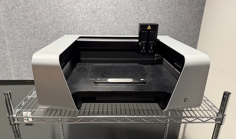
NOVA Setup
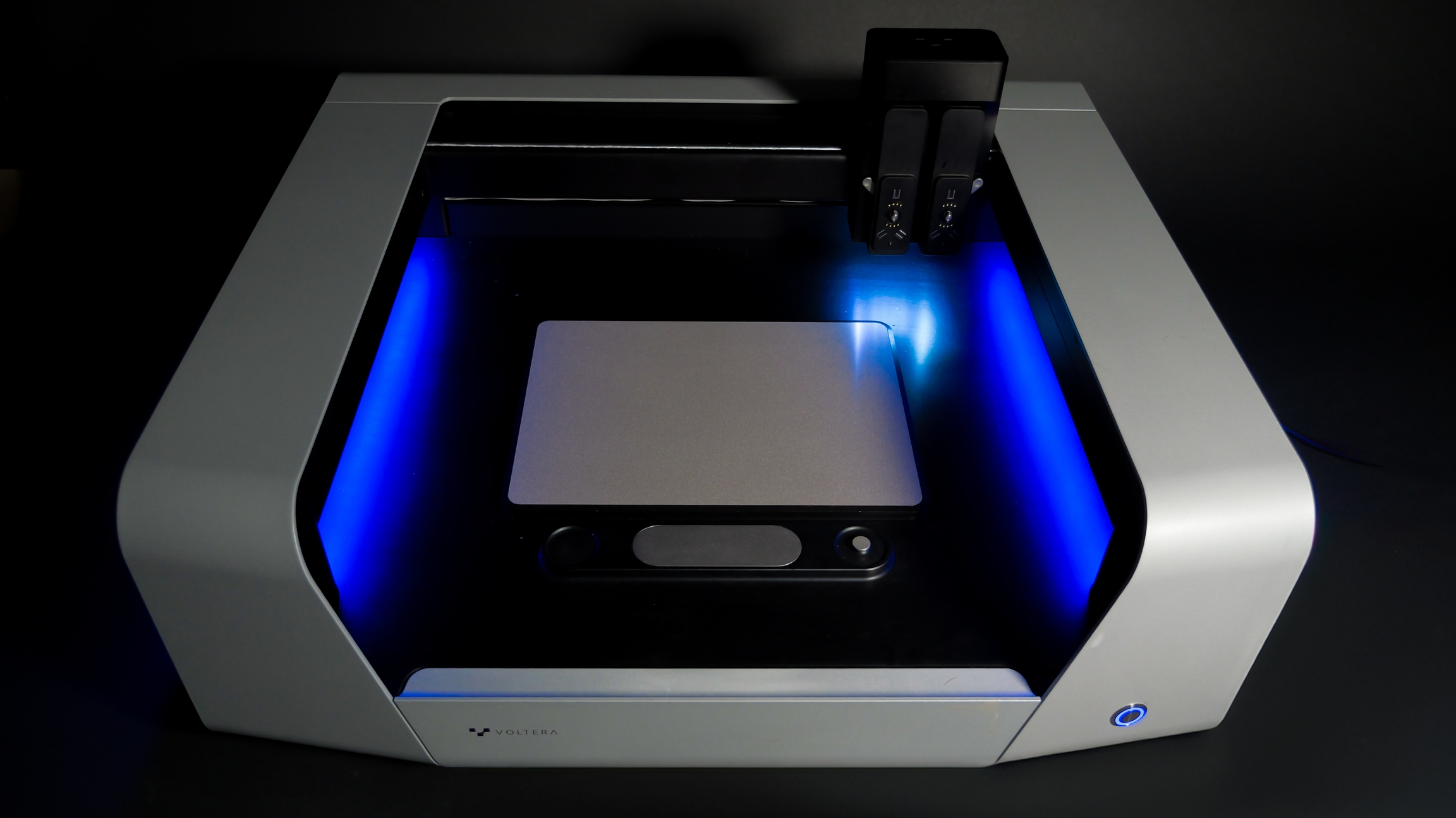
Ensure NOVA is placed on a flat, sturdy working surface. You will need to turn NOVA during this repair.
It's important that you have enough working room and a secure place to store loose screws and hardware.
Disassemble NOVA

Install the New Bridge
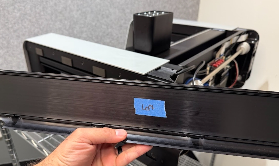
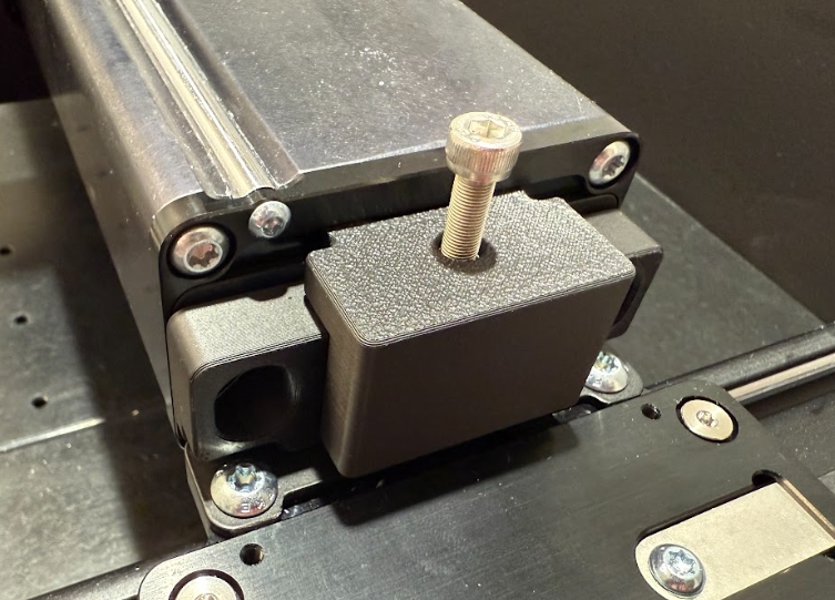
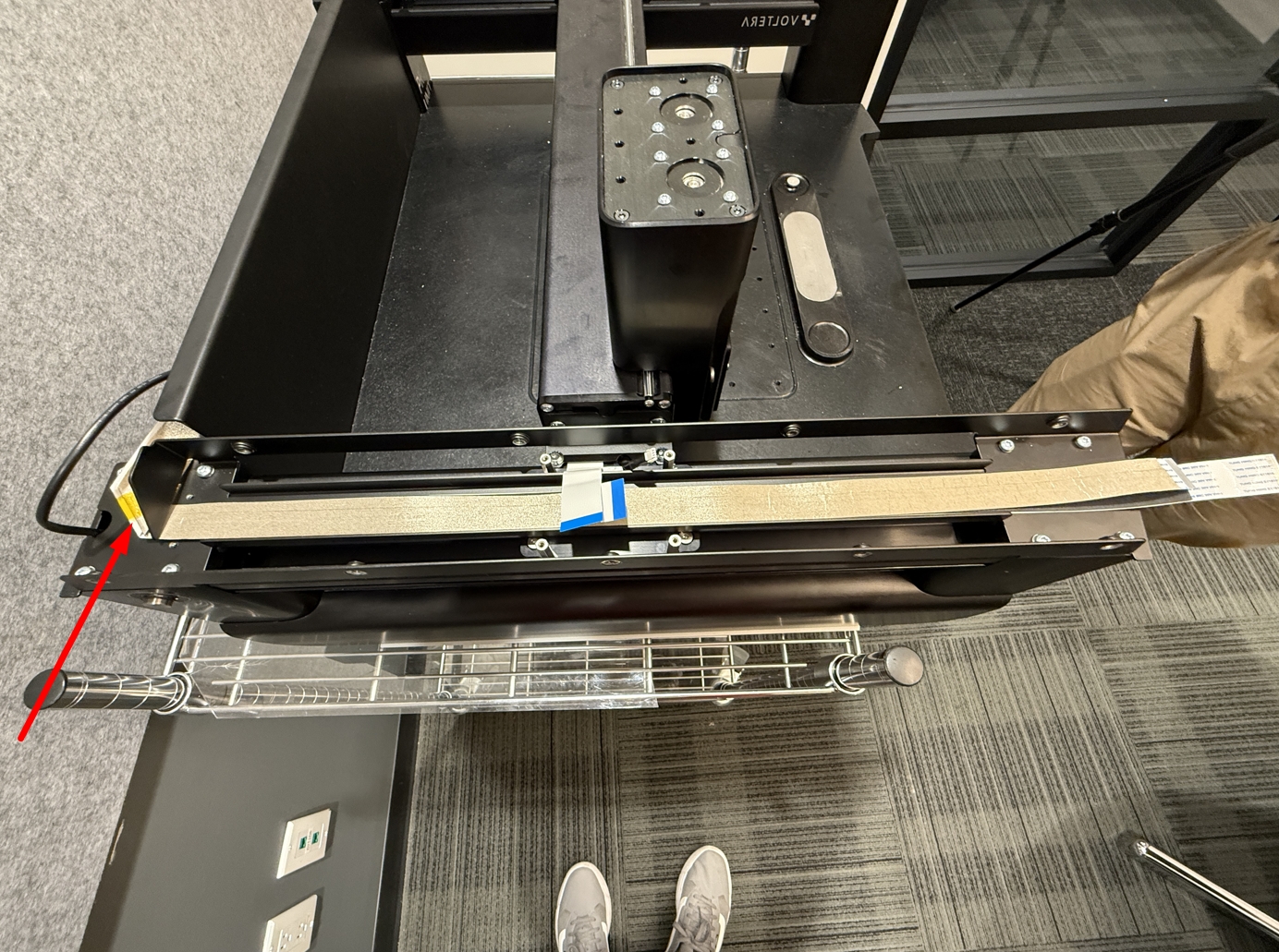
Install the new bridge
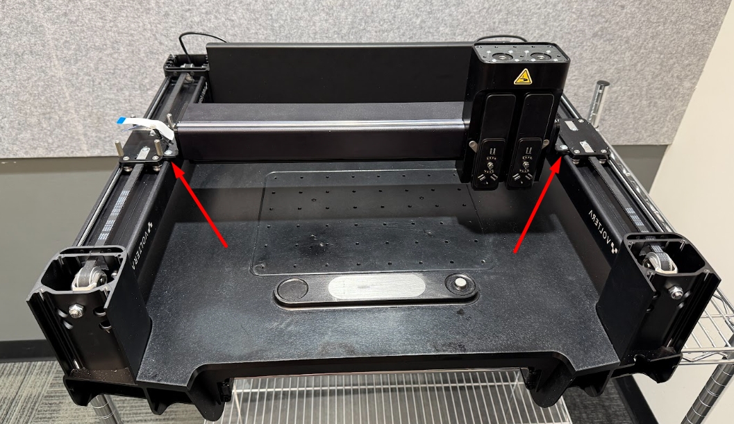
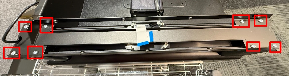
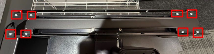
Install the new bridge onto NOVA. Using a T25 Torx bit tighten (Torque Setting 13 on Dewalt Driver) the 4 screws securing NOVAs bridge (2 left, 2 right).
If the screws look uncoated add a medium Loctite (liquid or paste is fine).
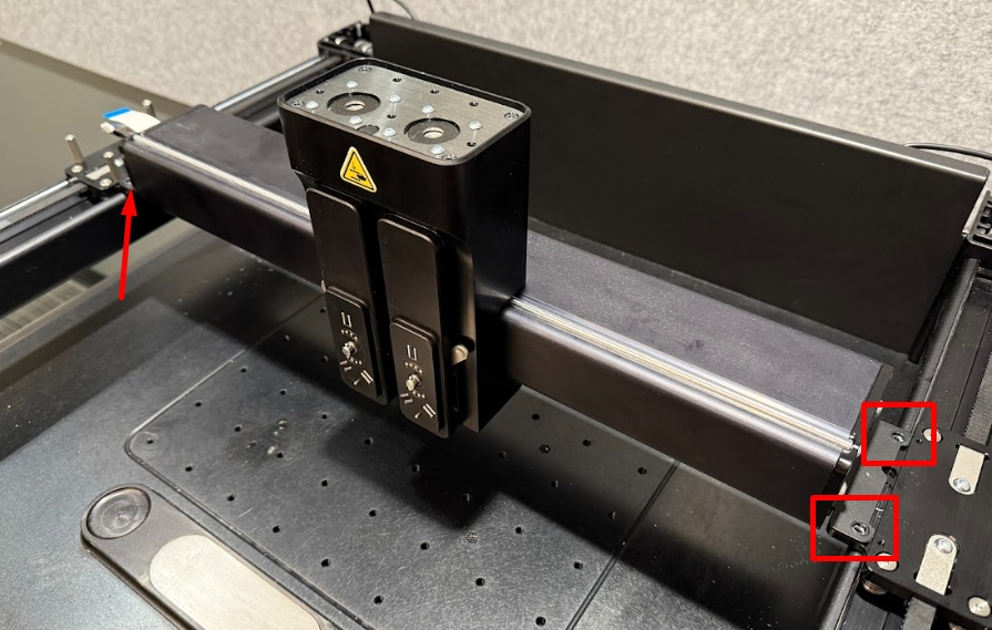
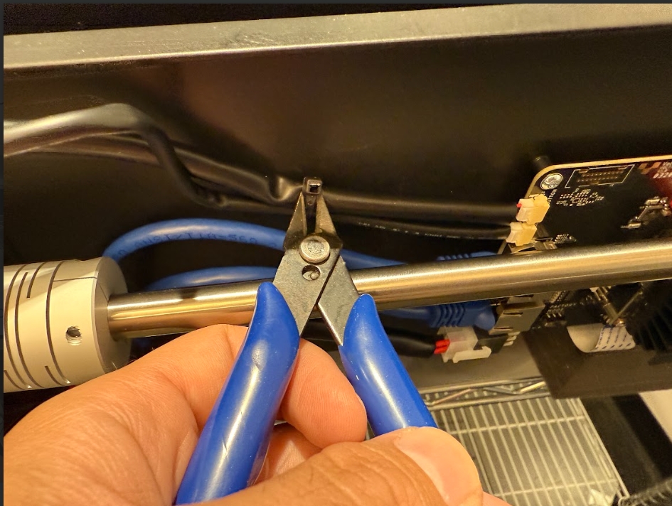
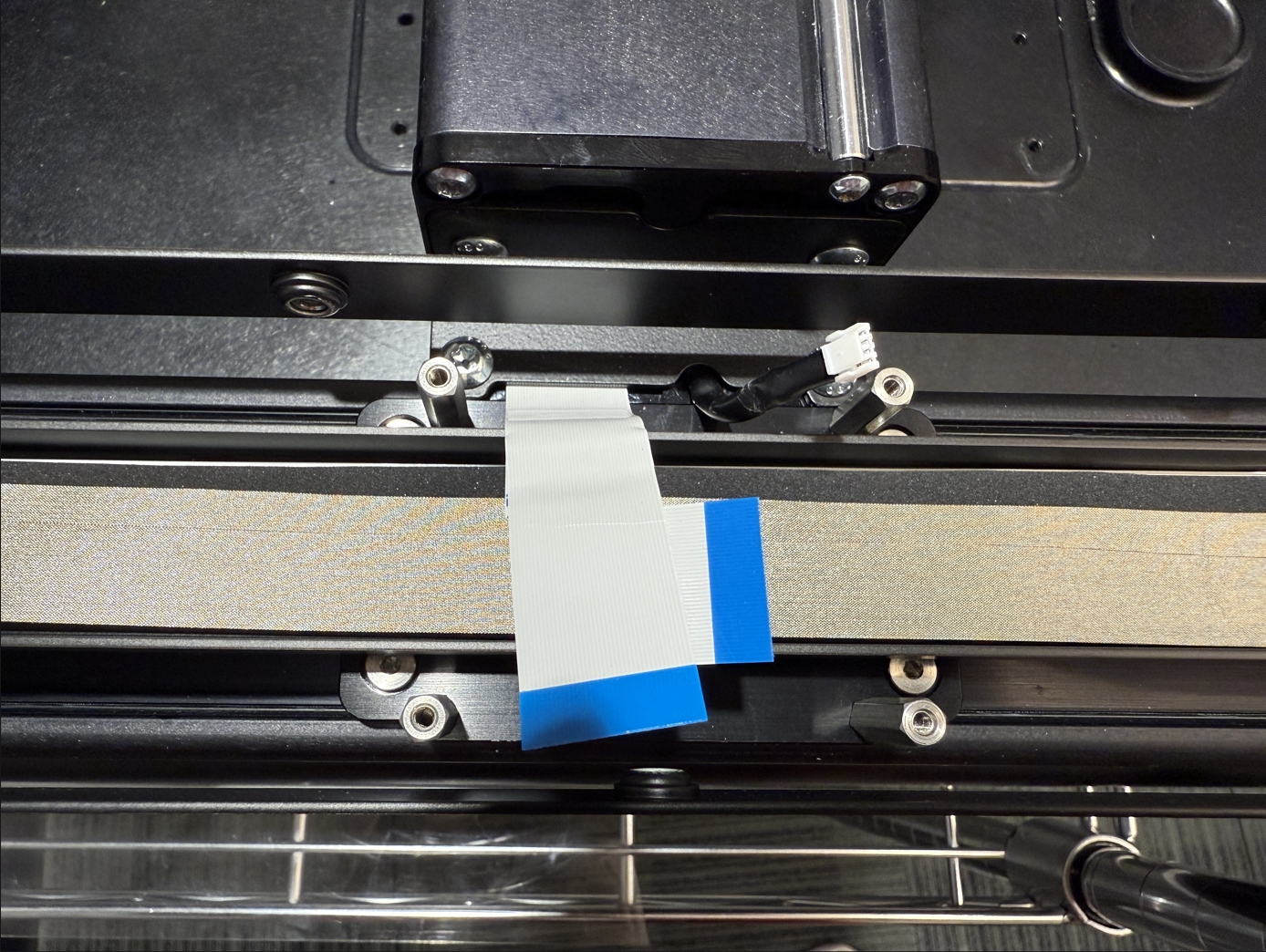
Ensure the cables on the bridge are in their appropriate slots and not being pinched by the bridge mounting bracket.
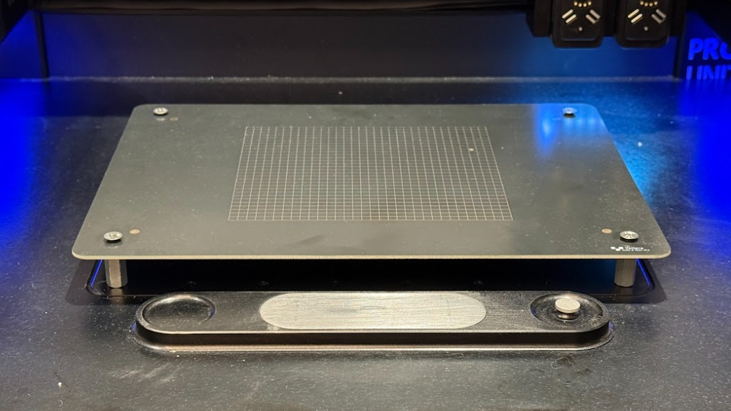
Level the bridge
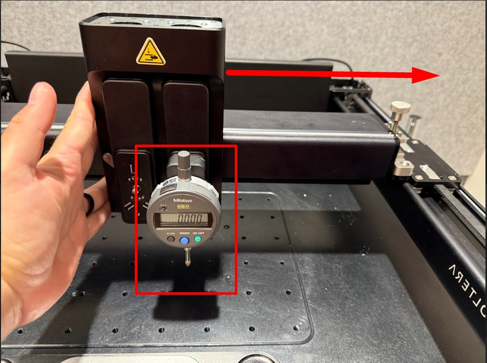
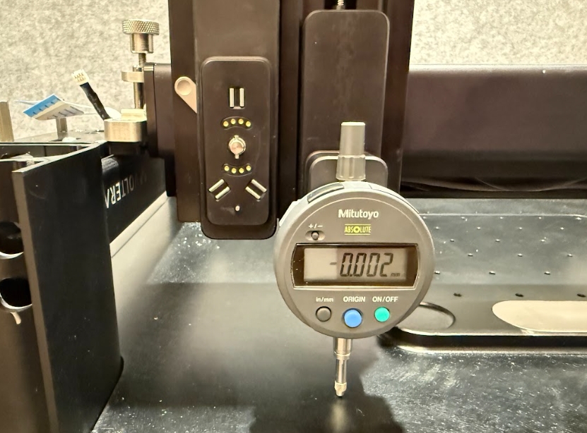
Bring the bridge to the front of NOVA and manually lower the tool port by pressing down on the top of the port with your thumbs. Lower the tool port until the dial indicator pushes into NOVAs body.
Turn the dial indicator on. Press and hold the ORIGIN button to zero the dial indicator. Take note of the value on the dial indicator.
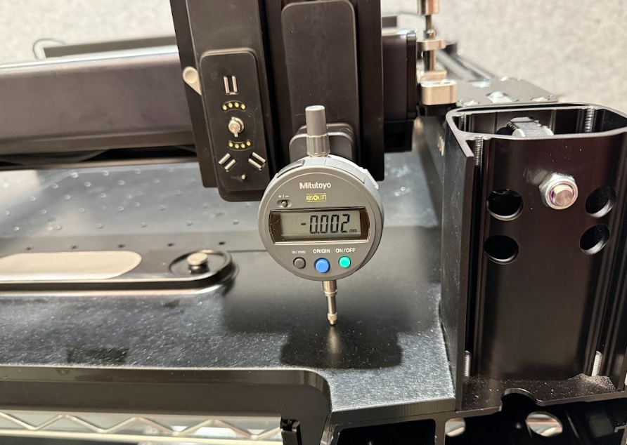
Push the module hub across NOVA to the very left side.
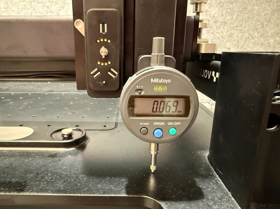
Now take note of the new height value.
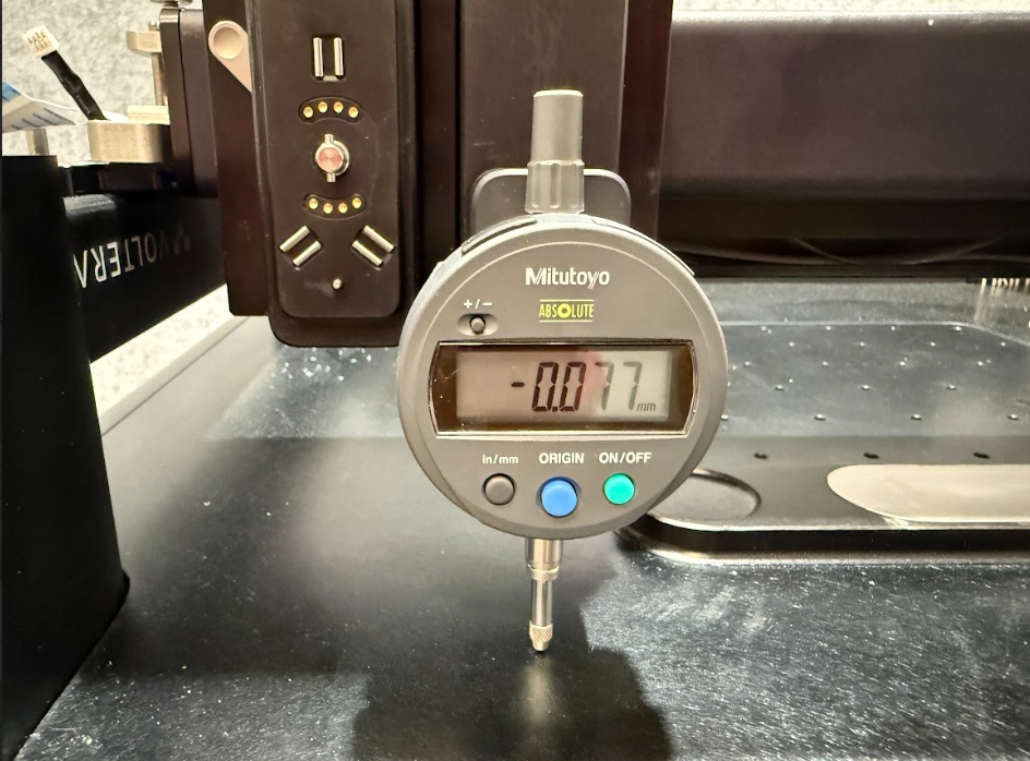
Select the tab below based on if you dial indicator is displaying a positive or negative number.
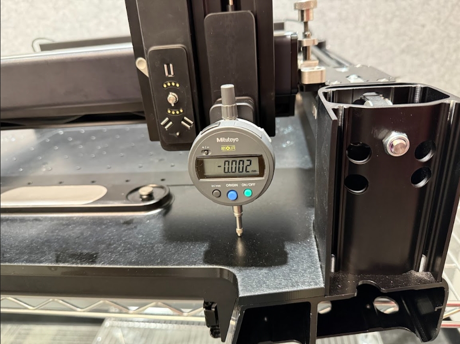
Place the bridge levelling jig on the LEFT side of NOVAs bridge (Low side).
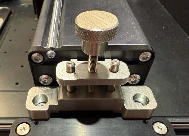
Using a T25 Torx bit lslightly loosen the 2 screws securing NOVAs bridge to the mounting bracket.
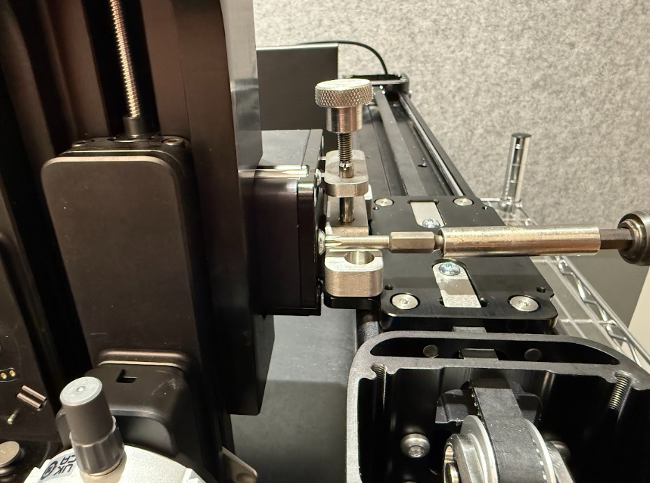
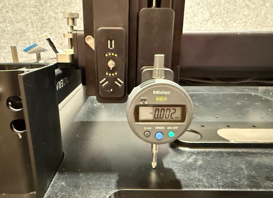
Rotate the bridge levelling jig clockwise using your finger or a M3 hex key to raise the bridge. Stop when the dial indicator reaches close to 0.000 (±0.010).
Using a T25 Torx bit tighten the 2 screws securing NOVAs bridge to the mounting bracket to lock in the height. Torque Setting = Dewalt Driver 13
Now push NOVAs module hub back to the very right side of NOVA to confirm that the height is within 100µm (0.100mm) of the left side.
The bridge must be level to within 100µm (0.100mm) on either side for factory specification. We always try to get as close to 0.000 within reason!
Move the bridge levelling jig and adjust the height as required.

Reassemble NOVA
Install NOVAs cable trays
If you are using an electric screwdriver start all of these screws using a hand screwdriver to ensure they thread properly. These screws are self driving and have a risk of rethreading the frame!
With a T20 Torx bit attach NOVAs cable trays using the 8 screws and serrated washers securing NOVAs left and right cable trays (4 in the back and 4 in the front). Torque Setting = Hand Tight
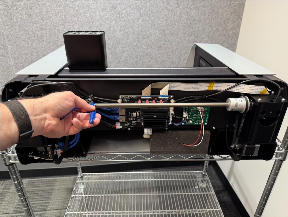
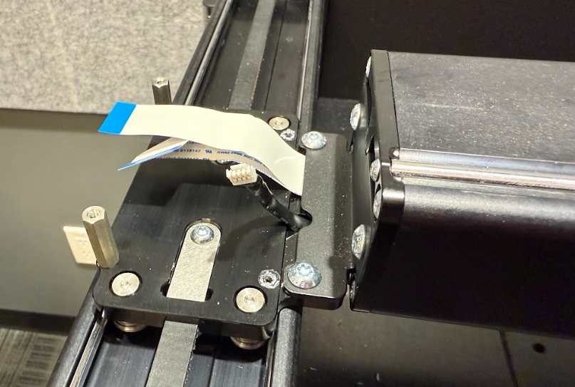
Install the Y-carriage PCB
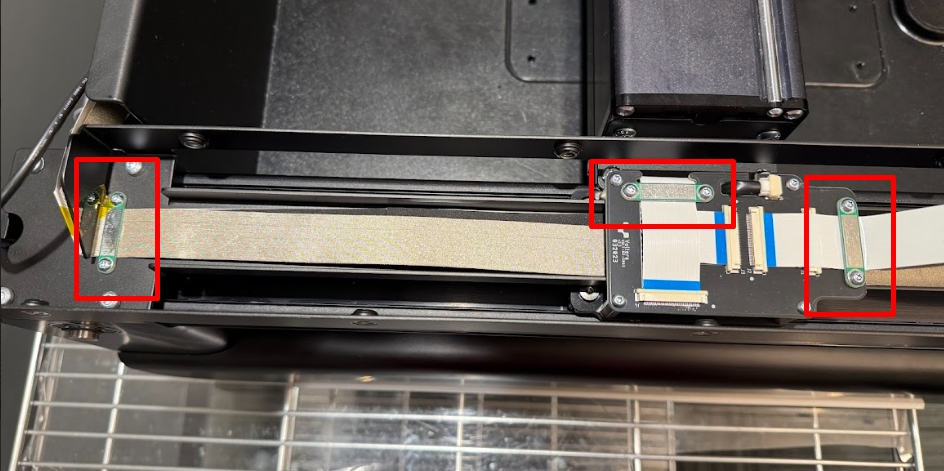
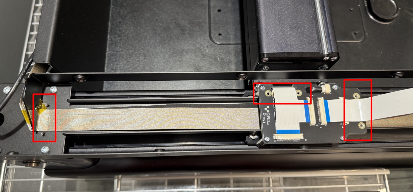
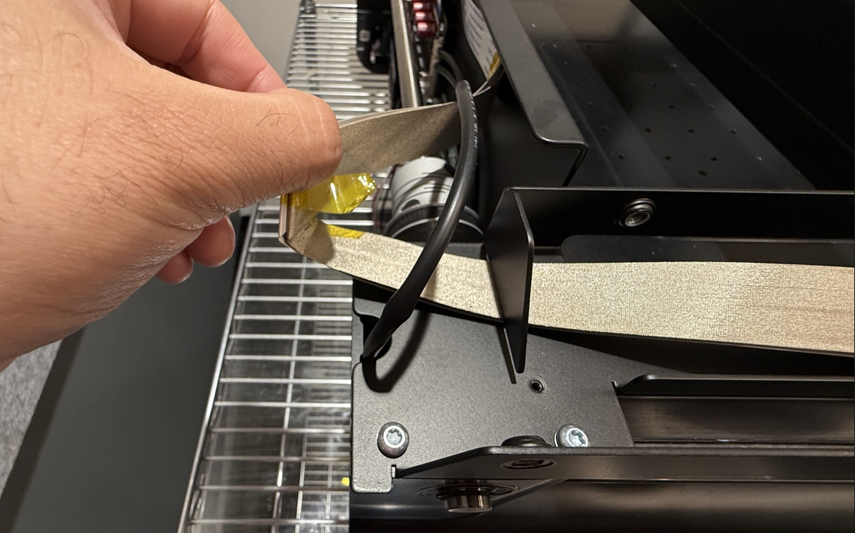
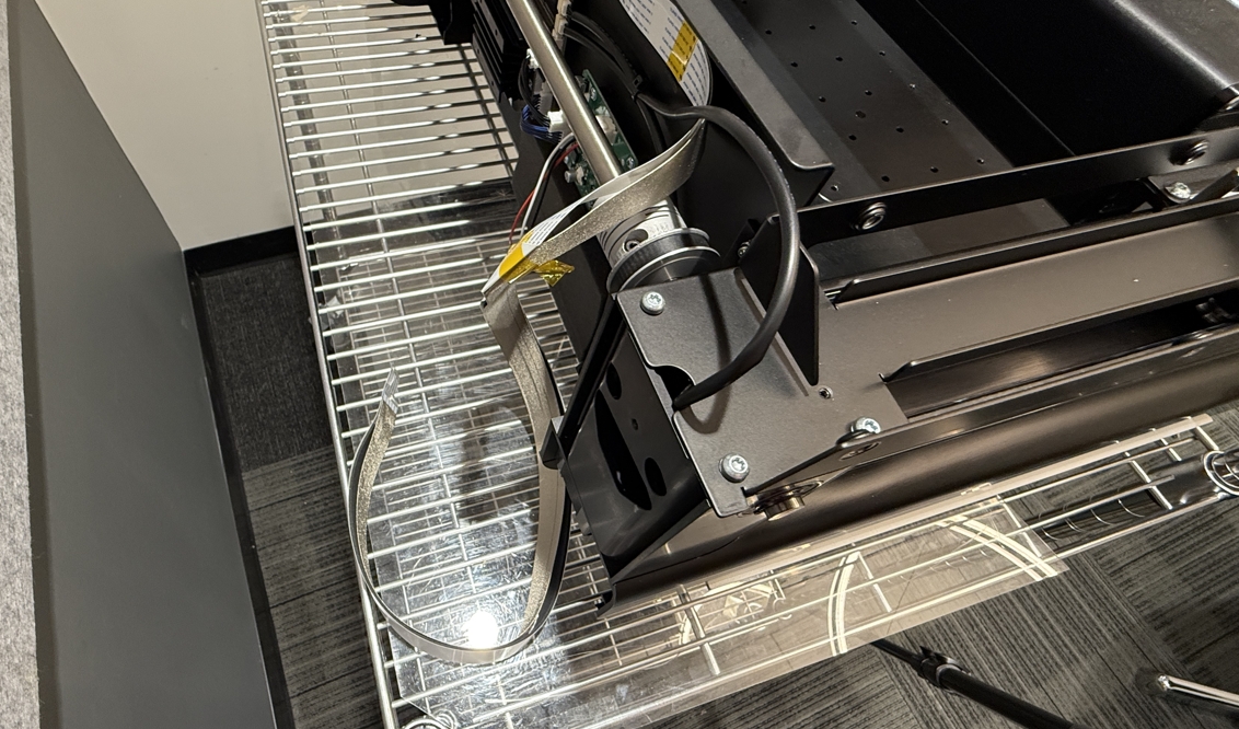
Replace the gantry ribbon cables on top of the cable tray.
Using a T10 Torx bit attach the Y-carriage PCB using the 4 screws (M3 x 0.8 x 6mm Button Head). Torque Setting = Dewalt Driver 8
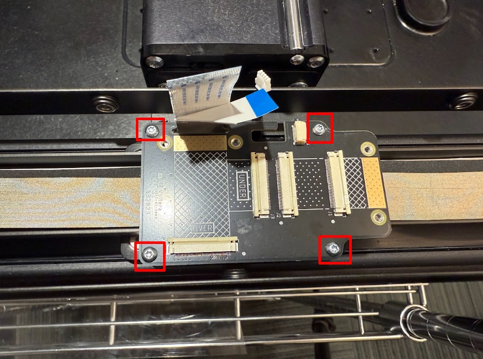
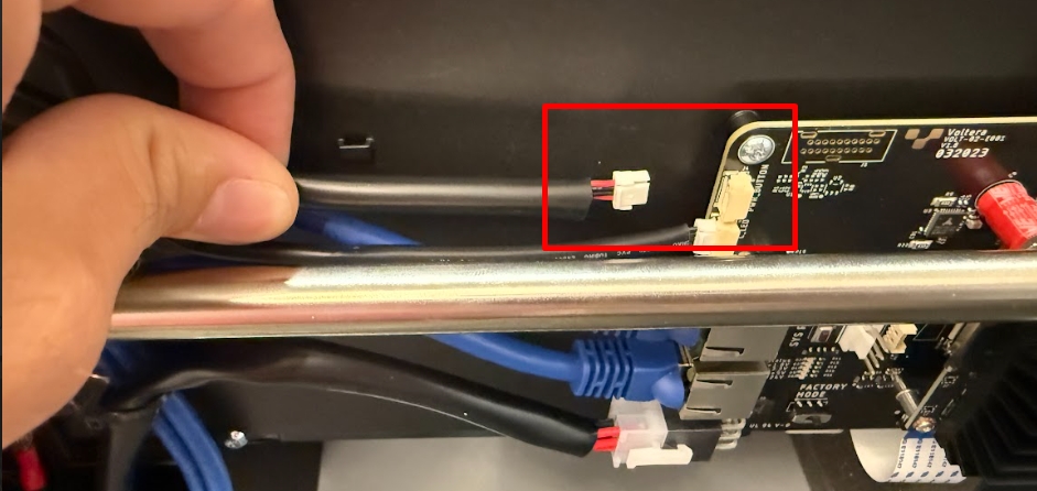
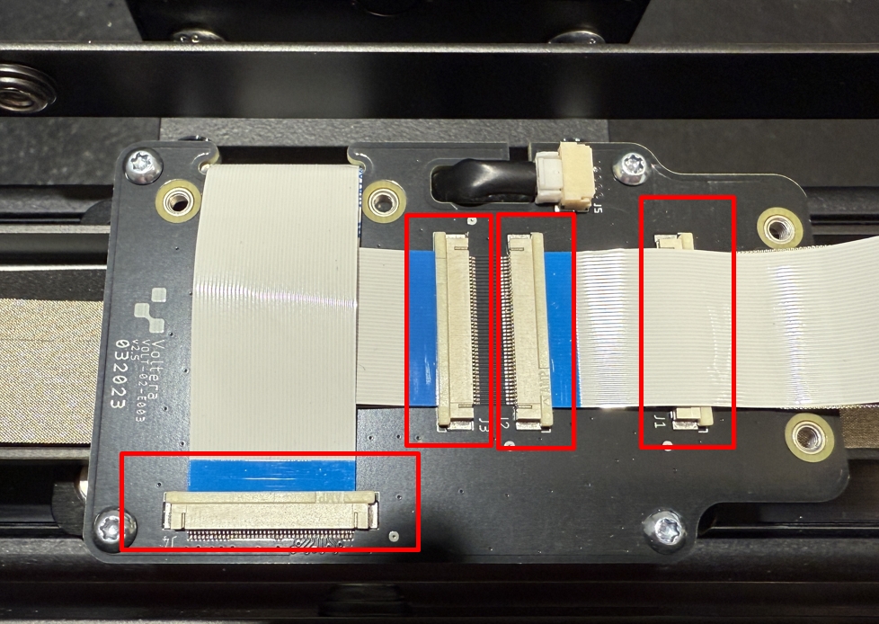
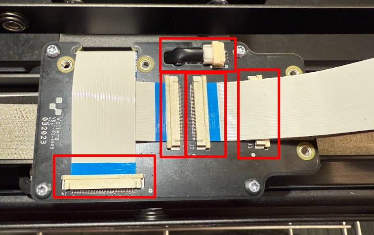
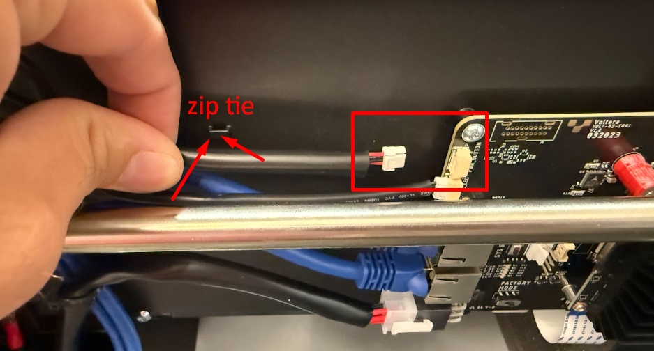
Connect the 4 ribbon cables and the black motor cable to the Y-carriage PCB.
Ensure the cables are fully inserted into the connector. The blue tab should be parrallel to the connector.
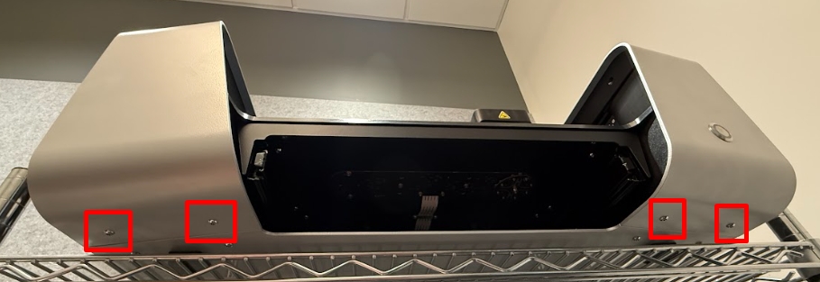
Install NOVAs side fenders
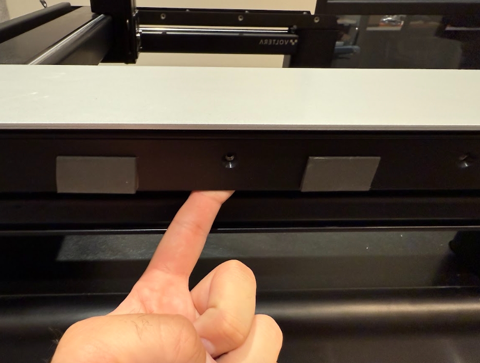
With a T20 Torx bit install NOVAs side fenders. There are 11 black screws that secure each of the fenders (5 on the outer side, 4 on the inner side, and 2 on the bottom side). Torque Setting = Dewalt Driver 13
Attach the bottom screws last. Torque Setting = Dewalt Driver 13
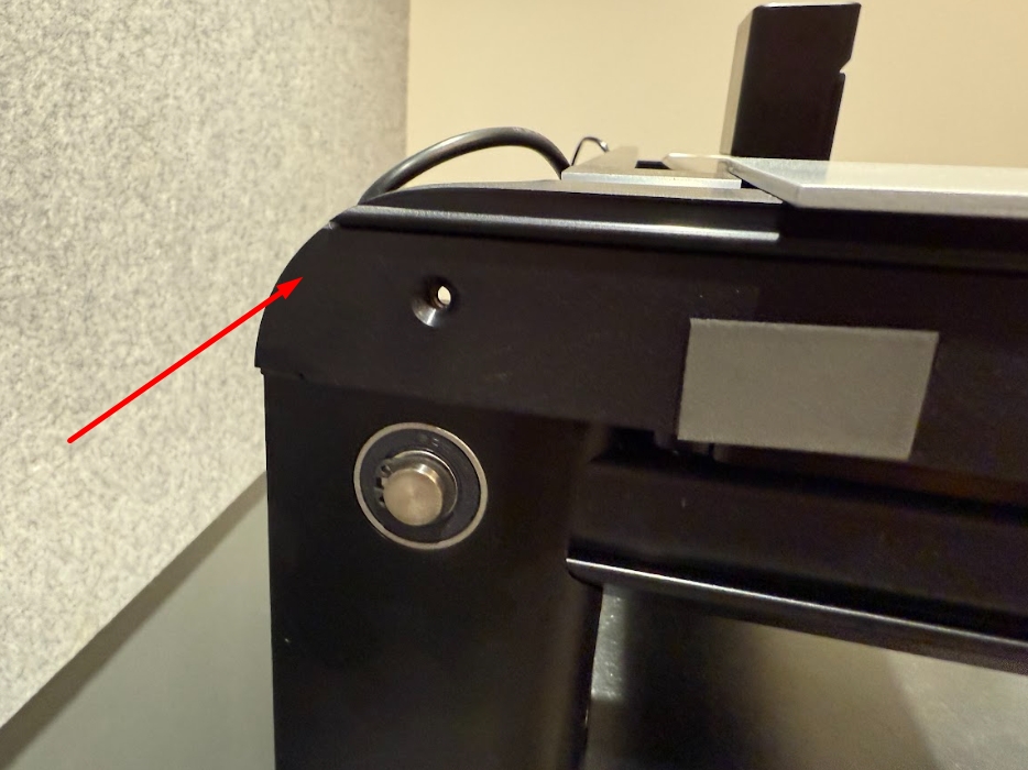
Ensure that the fenders are aligned properly at the back of NOVA.
You may need to pull the cable tray out with your finger to thread the screws.
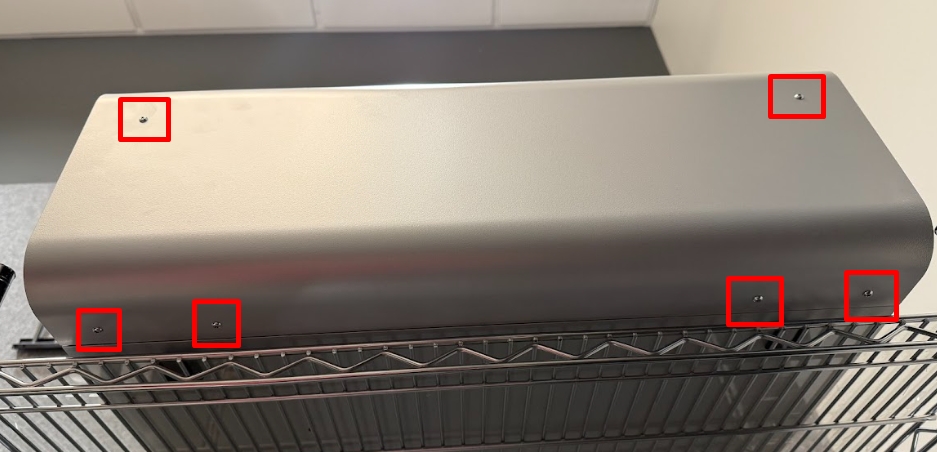
Install NOVAs back plate
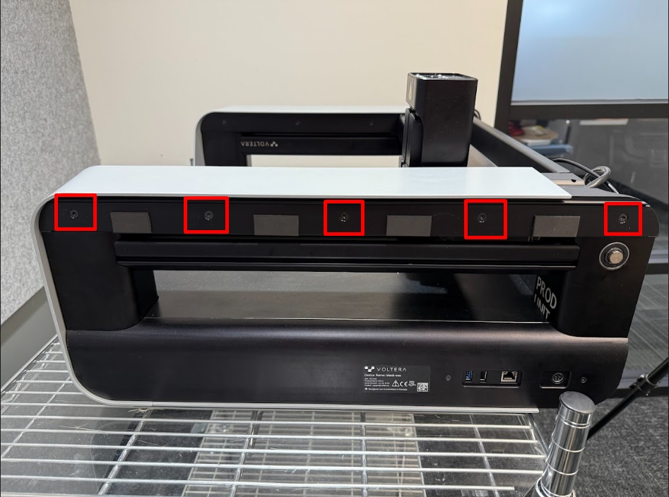
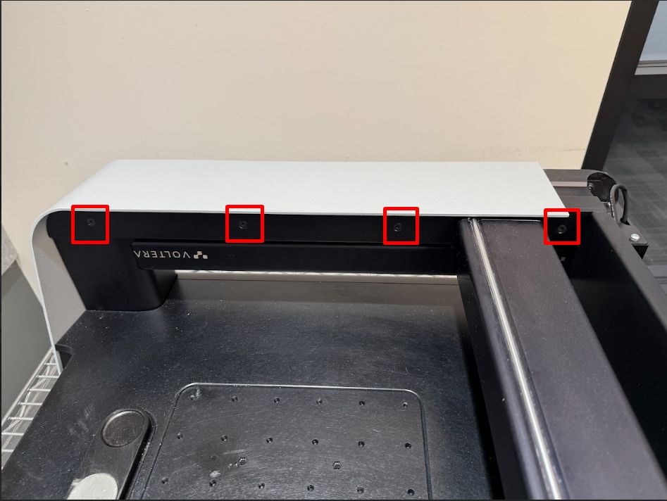
With a T20 Torx bit install NOVAs back plate. There are 6 screws (2 on the back side, 4 on the bottom of the panel) securing the back plate. Torque Setting = Dewalt Driver 13
You can leave NOVAs back plate off until after you complete the calibration procedures in case of potential troubleshooting.
Re-calibrate NOVA
With NOVA reassembled, you will need to run through a few factory calibration procedures. The order for these are as follows:
Set backlash values
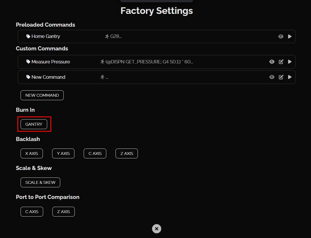
Run gantry burn in for 30 minutes
Test the port to port values
Calibrate scale and skew
Calibrate the camera
Run alignment calibration
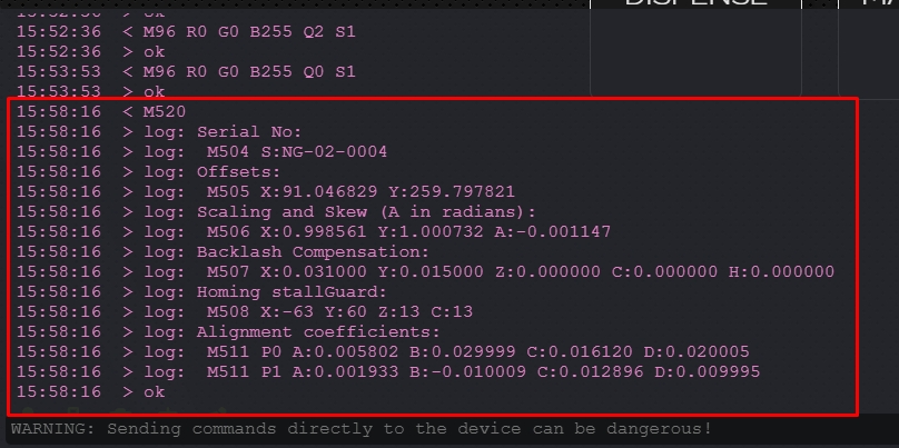
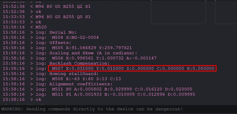
Set Backlash Values
Gantry Burn In
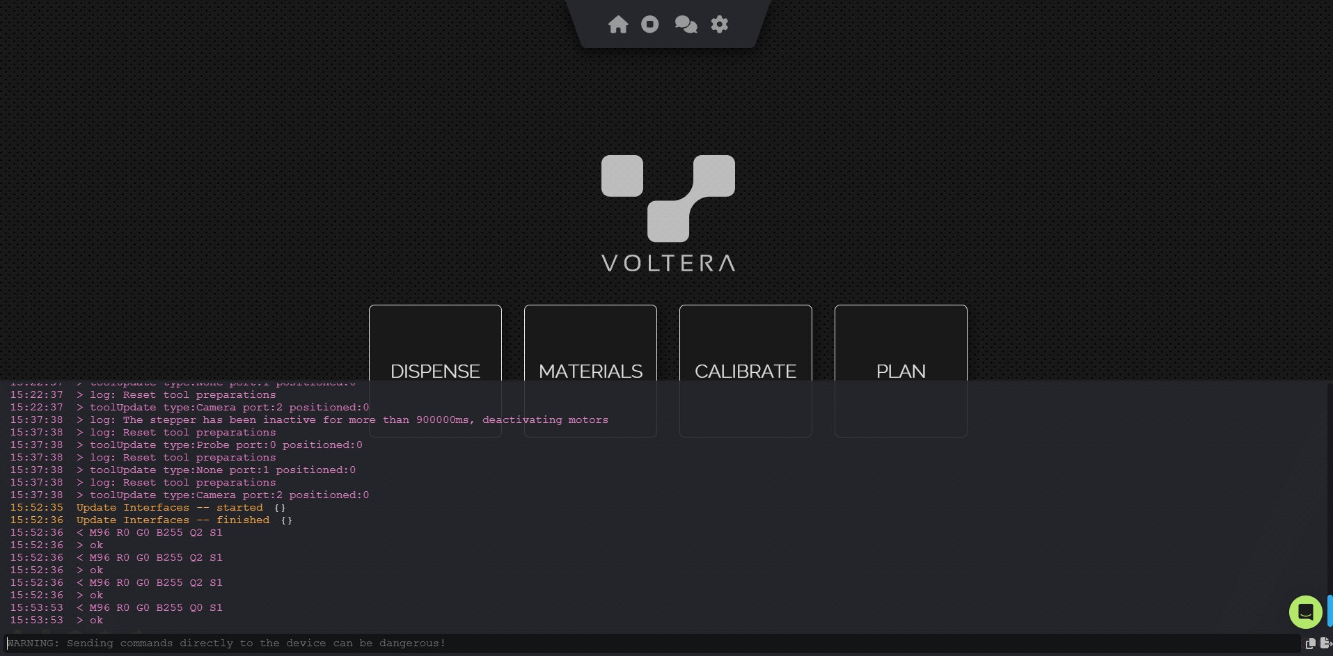
Access Factory Settings
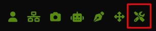
The gantry burn in is hidden in a factory settings menu. To access this you'll need to press Shift + 2 + 4 on your keyboard. If your keyboard is international, the keys you'll need to press are @ + $ where ever they are placed on your keyboard. In factory mode a few more icons are visible in the bottom left menu. Click on the tools icon to open the factory settings:

Port to Port
Run Port to Port for Z Axis
Next, place the probe on the right port and run the Port to Port Comparison for the Z Axis. This will have the probe measure the same grid of points across the vacuum module of the bed. Again, once complete the gantry will return to the home position and you can remove the probe.
Download the Data
The results of this test are stored locally as a CSV file for each port in a data folder on NOVA. To access them add /data/factory to the machine's browser address. ex. cool-sea.myvoltera.io/data/factory or 10.42.2.1/data/factory
Search in this folder for the CSV files of portToPort-0 and portToPort-1 with the date you ran the test and click on them to download.
Send Voltera the Files
This test is done before the replacement bridge is sent out and running it again on the new machine is an extra check to make sure nothing has happened to the bridge in transit. Because of this, the simplest way to analyze the data currently is to send it to [email protected] and we can double check it.
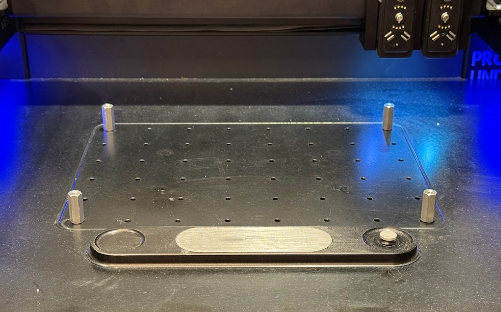
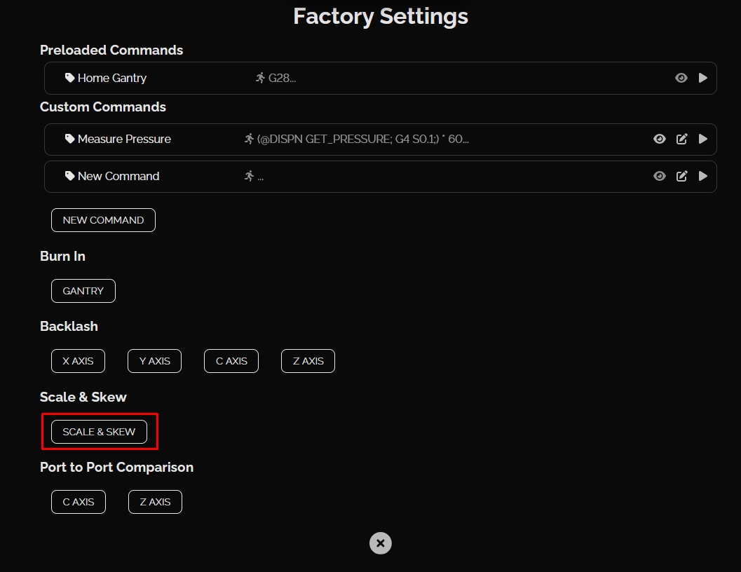
Scale & Skew

Camera Calibration
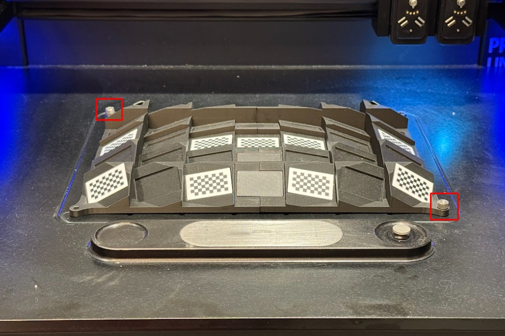
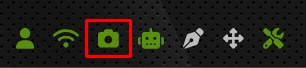
Run the Calibration
Under the camera stream there is an icon that looks like a factory. Click on this to start the camera calibration.
The calibration will take a series of pictures across the surface of the jig. It will then pause for a moment to make some calculations. It will then take one final picture in the center of the jig. Once complete it will home the gantry.
Confirm the Calibration
The results of the calibration are stored locally on NOVA. To access them add /data/calibration to the machine's browser address. ex. cool-sea.myvoltera.io/data/calibration or 10.42.2.1data/calibration
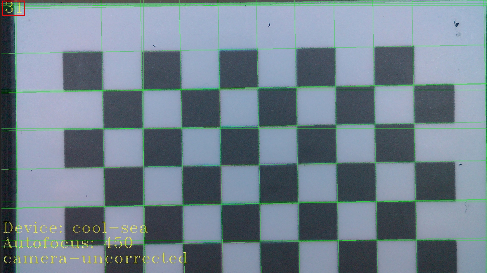
You should see to jpg files labeled device-name-camera-corrected.jpg and device-name-camera-uncorrected.jpg Open the uncorrected image first by clicking on it and take note of the number of lines detected in the top left corner (ex. 31):
Click back in the browser to return to the calibration files page and open the corrected image. The number of lines should be smaller than the uncorrected image (ex. 27):
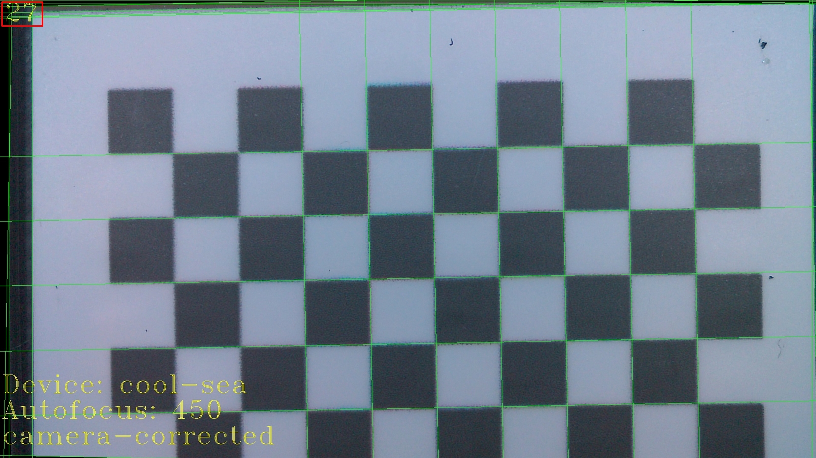
If the number of lines is not smaller than the calibration needs to be run again. Double check that the jig is flat on NOVAs surface.
Alignment Calibration
Because you've attached a new bridge, the relationship between the tools center and the camera center will be deferent than previously recorded (if the calibration had been done).
To do this calibration you can follow our existing guide:
Repair Complete!
Congratulations, you have successfully replaced NOVAs bridge!
Please reach back out to our support team through email ([email protected]) or the chat to let them know everything went well. We will arrange a shipping label to return the old parts and repair tools back to us for further testing.
Last updated
Was this helpful?